
It’s finally time to get back some of the power that was robbed from me when I moved from sea level (Seattle) to high altitude (Denver)! I’ve decided that forcing more air into the engine with a centrifugal supercharger is my ideal solution due to cost, complexity of the install, driving dynamics and longevity potential for my engine with 200,000+ miles on it. Centrifugal superchargers are driven by the accessory belt (same belt as the alternator) and thus in a static speed ratio with the engine. Put another way, as you increase engine RPM, you’ll also increase supercharger RPM at the same rate and the associated boost pressure that it’s providing. Because of this, the engine has the same general characteristics of a naturally aspirated engine but it just has more power from mid-range to red-line.

Vortech is known as the industry standard manufacturer of centrifugal type superchargers and has been for a quite a long time. They make several different centrifugal supercharger models that tuner houses then assemble into kits with brackets, piping, wiring, etc in order to make it easier to install them into specific cars. I was able to secure such a kit produced by VF Engineering that had previously been used on an S50 equipped BMW E36 M3. The M50 in my E36 and the S50 engine in the M30 are identical externally so the kit is interchangeable between the two engines. The only thing that would most likely need to change is the flow rate of the injectors as my M50 is 2.5 liters and the S50 is 3.0 liters (so the S50 will need more fuel).

The VF Engineering kit that I acquired was advertised as a complete kit but I knew there would be small parts here and there that I would need to secure separately. A complete kit would be the following:
- Vortech V2 centrifugal supercharger with pulley
- Intake tube from the V2 to the MAF (including screw clamps)
- Tube/coupler from MAF to air filter (including screw clamps)
- Cone air filter
- Bracket for mounting the V2 to the engine with necessary bolts
- Charge pipe from V2 to the throttle body (including t-bolt clamps)
- Bypass valve with tubes connecting charge pipe to intake tube (including screw clamps)
- Idler pulley to mount to V2 bracket
- Modified top radiator tube (so it doesn’t impact pulley on V2)
- Oil dipstick tube from M52/S52 engine to allow oil to drain from the V2 back into the pan (needs to be modified further by removing lower sheath around section that goes into the pan)
- Fuel line (1/2″) for oil drain from V2 to dipstick
- Extended M14 x 1.5 banjo bolt that allows two banjo fittings
- Banjo fitting with -4AN barb
- V2 oil feed line with -4AN fittings on each side (I used 18″ length)
- -4AN barb fitting on V2 oil feed
- Vacuum check valve for brake booster (maybe not technically needed but I did it for peace of mind)
- Fuel injectors (I ended up with 30 lb-hr from the VF kit)
- Vacuum lines and T’s
- 16 AWG wiring to extend MAF wires
- Extended length accessory belt
- Boost gauge with holder (optional but highly recommended)
- Wideband oxygen sensor and gauge with holder (optional but highly recommended)
- Modified OBD1 chip for the DME (computer)
- 2000k ohm resistor for MAF wiring
As you can see, the list is pretty extensive with lots of little small parts. I tried to think everything through before I started but I still had to purchase some little parts here and there through the install process when what I had didn’t quite work. My E36 was on ramps in my garage for the best part of two months while I did this install in phases and waited for parts to arrive. I would go pump up some Metallica, Weezer, Red Hot Chili Peppers or a technology podcast (ha ha!) in the garage and jump into the installation for a couple hours before my three small kids pulled my back into the house to play.
Below are a few pictures taken during the installation process. Descriptions are directly under the pictures.

This is the dual banjo fitting setup on the extended banjo bolt that normally only feeds the Vanos line. Now there is one banjo fitting feeding the Vanos while the other banjo fitting is supplying pressurized oil to the supercharger.

Check valve on the brake booster so the booster will only see vacuum (not boost). Makes me feel better to have it there.

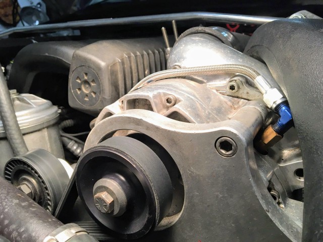
Measuring for the correct length accessory belt using a longer accessory belt that came with the kit. Remember that I don’t have a power steering pump so I need a shorter belt. You can also see the pressurized oil supply line feeding into the supercharger at the blue AN fitting. The oil return line connects directly underneath the supercharger next to my fuel filter.
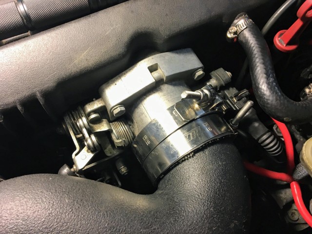
I used t-bolt clamps to secure all of the pressurized pipes to create a strong bond around the entire coupler and prevent boost losses (or vacuum leaks). Screw clamps just can’t get tight enough in my experience. Also make sure to orient the ones on the throttle body so that they don’t interfere with the throttle mechanism.
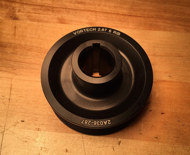
I had to switch to a smaller 2.87″ diameter pulley in order to bring the boost up to the normal 6-7 psi maximum due to my high altitude. Normal size for the kit is 3.60″ so this is quite a decrease in size. A smaller pulley simply makes the supercharger spin faster per revolution of the engine.

The actual install of everything went fairly smoothly when I had the correct parts. The most challenging parts of the install were modifying the M52/S52 oil dipstick tube to work with the M50 pan and then figuring out what flow rate injectors to use. There are two main things that need to be done with the oil dipstick tube in order to make it work properly as an oil drain for the supercharger. First, remove the lower sheath (I used a Dremel tool) and now it will be able to slide into the M50 oil pan. Next, drill a few holes in the internal tube where the the drain branch joins the main tube. This will allow oil to flow into the main tube instead of down around the sides of it. You’ll be able to see what I mean when you have the actual tube in front of you.

The injectors that came with my previously used kit were dark red topped but have the part numbers scratched off so I don’t know what the flow rates are for them. However, once I got the car all put together (with the wide-band O2 sensor/gauge installed) it would idle very erratically and the Air Fuel Ratio (AFR) was showing around 9:1 which is incredibly rich. Bummer! I assumed that I had a vacuum leak somewhere that was causing this very rich condition. My boost gauge also showed a vacuum level that wasn’t where I wanted it to be but the engine was cold so it should be showing somewhat low.

After making sure that all the screw and t-bolt clamps were tight, I let the engine idle as best as it could and then sprayed down several suspect areas in the intake tract with brake parts cleaner to see if the added fuel would cause the engine to momentarily idle at a higher RPM. The engine didn’t react with an increased idle no matter where I sprayed so it looked like a vacuum leak wasn’t the cause of the rich running condition. It was at this point that I decided to just install the stock injectors to see if I could get the car to idle properly. Sure enough, with the stock injectors installed my BMW idled perfectly with an AFR around 13.5 (with a nice smooth whistle from the supercharger).

I took the car for a quick drive around with a eye on the AFR gauge. As soon as the boost came on I could see the AFR climbing into the high 13’s so I didn’t let the engine speed build very high. However, the car drove well without any issues. Now I knew that I had to get some different injectors that would fit the OBD1 chip tune and keep the AFR in the 11:1 to 12:1 range through all engine speeds up to the maximum boost of around 6-7 psi at red-line.

Luckily there’s no need to look for expensive BMW Bosch injectors as Ford Mustang 5.0 injectors from the mid-90’s are the exact same form factor and connectors. Plug-and-play match for my E36. I took a chance by purchasing some used real Bosch 24 lb-hr injectors from a performance shop that had been flow tested and performance checked (with new o-rings and caps). They arrived and everything fit perfectly as I hoped (though of course they made me buy a set of 8).
After starting my E36 up with the new injectors the great idle was back! The AFR at idle was right about 13:1. I was definitely excited to get it out on the road and do a shake-down run to make sure it was running the right boost level and AFR was where it should be through the entire engine speed range. Just hearing the supercharger whistle was really cool! I was very relived to see that AFR drop down to mid-11’s whenever I went wide-open throttle at most any RPM. Up near red-line the AFR would be low 12’s which may not be perfect but should still be just fine when only running 6-7 psi of boost.
UPDATE: It turns out that I had forgotten to install a resistor in the yellow MAF wire that VF Engineering requires to use their chip. My understanding is that the resistor is effectively used to scale the voltage from the MAF so it doesn’t top out at its 5V limit before hitting maximum RPM. So, in effect, it actually leans out the AFR and advances the timing. Thus, when I added in a 2000 ohm resistor (1000 ohm comes standard with the S50 kit) and reinstalled the VF Engineering injectors (which are 30 lbs according to them) then the car ran absolutely perfectly. This is the configuration that I’m running now.

Speaking of boost, it definitely comes on around 3,500 rpm where it’s at about 3 psi and then builds fairly linearly until it’s at about 7 psi at red-line. You can feel the increase in power compared to stock though it’s not a huge kick in the pants at low rpm like a turbocharger would be (remember, I had a 18 psi boosted Porsche 944 turbo with a giant turbocharger so I know what that feels like). It’s easy to control the power of the engine which should be good when maintaining speed around autocross corners and through slaloms.

Hard work has paid off! I really like the characteristics of the centrifugal supercharger on this engine and it more than makes up for the high altitude now. My car is now at a power level where I think I should be happy for quite a while as it feels like the chassis, suspension and brakes are in balance. It’s at a level where it’s a blast for me to drive and be competitive in but it wouldn’t be overwhelming for an autocross novice to jump in and take it for a run. The noise inside the car when driving it hard is pretty amazing now because of the total lack of sound deadening, delrin engine and transmission mounts, stiff suspension bushings and supercharger whine with just more air being forced into the engine and out of the exhaust. Success!
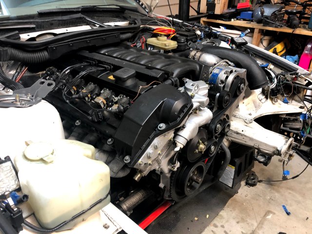
Update: I recently performed an S52 engine swap and I was able to take some interesting pictures of my E36 with the whole front end off. It gives a pretty cool perspective of the supercharger installed that you don’t normally see. Take a look!


If you liked the information in this page, be sure to check out my Developments page for my most recent posts! Every single post is listed with a link on the Headquarters page.
Links:

I would like to know what maf you ran with this set up. Did you use stock or a 3.5 maf? If you could email me that would b great
LikeLike
Kailub, I’m still running the stock 3″ OBDI MAF (Mass Airflow Sensor) in the car. In my discussions with TRM (my tuning chip provider), they think that I might have to move to a 3.5″ MAF when I installed the S52 in place of the M50. So far everything is working great with the 3″ MAF on the supercharged M50. Thanks!
LikeLike
Your article help me alot,
I just bought supercharge kit and the belt did’t come with, May i ask what size for the belt.
Ps. sorry for my eng
LikeLike
Great to hear that you found the information helpful. I’m actually using a Gates K060785 belt that’s 2007mm (79.034″) in outer circumference. Remember that I don’t have a power steering pump though. If you’re still using your power steering pump then you’re going to need a longer belt. Thanks.
LikeLike
hey are you using the chip inside a 413 red label ecu?
LikeLike
Yes, I am
LikeLike
I cannot find it anywhere on any internet search or threads. With the VF Engineering Supercharger installed, where specifically do you tap off of to connect to a boost gauge? I tapped off of the hose coming from the brake booster to the intake manifold and all I am getting is vacuum, no boost, no matter what RPM. People have mentioned that next to the connection of this hose to the intake manifold, on the intake manifold there is an unused plug that you can tap into, but I don’t understand how moving it 3 inches (from the hose location to the manifold location) would solve that. Any help would be greatly appreciated!!
LikeLike
I tapped into the vacuum hose that is under the M50 manifold towards the rear. I believe it’s also what the Fuel Pressure Regulator (FPR) is using as a reference signal. I just “teed” it from that. You can see it in this ebay listing in the first picture on the far upper right side:
https://www.ebay.com/itm/276034403674?chn=ps&norover=1&mkevt=1&mkrid=711-117182-37290-0&mkcid=2&mkscid=101&itemid=276034403674&targetid=1645685073768&device=c&mktype=pla&googleloc=1014462&poi=&campaignid=20379420840&mkgroupid=153074405882&rlsatarget=pla-1645685073768&abcId=9316476&merchantid=6296724&gad_source=1&gclid=Cj0KCQiA84CvBhCaARIsAMkAvkIpCDSHX2-RrX8HH_LveQ6UQd3I9AgSIWCgnFmILc7HJXACouMe1EMaAghREALw_wcB
LikeLike