
My new supercharged S52 requires a new clutch that can keep up with it without issue. One thing that I learned quickly when researching clutches is that there are a lot on the market for the BMW E36. The prices vary considerably and so do the reviews from those that have tried them.

After reading a ton about it, I decided to go the low cost route and try the “FX Racing Stage 2 Clutch + Chromoly Flywheel” for only about $250 delivered. Most of the reviews that I read were good, the price was amazing and this is not going to be a daily driver car. I can live with a lot as long as it holds the power!
Here are some of the highlights noted from the kit description:
- Heavy-Duty Pressure Plate with Single Diaphram Design
- Stage 2 HD Carbon Kevlar Sprung Disc (9.5″), Heat Treated Springs and Retainer Rivets
- 4140 Forged Chromoly Steel One Piece Flywheel, Fully Balanced, Meets/Exceeds SFI 1.1 Specifications, Tested to 12,000 RPM
- Stated Horsepower Rating: 403 HP
- Stated Torque Capacity: 342 Ft/Lbs
I also purchased a German made Pilot Bearing. When it comes to bearings, I think you need to go higher quality.
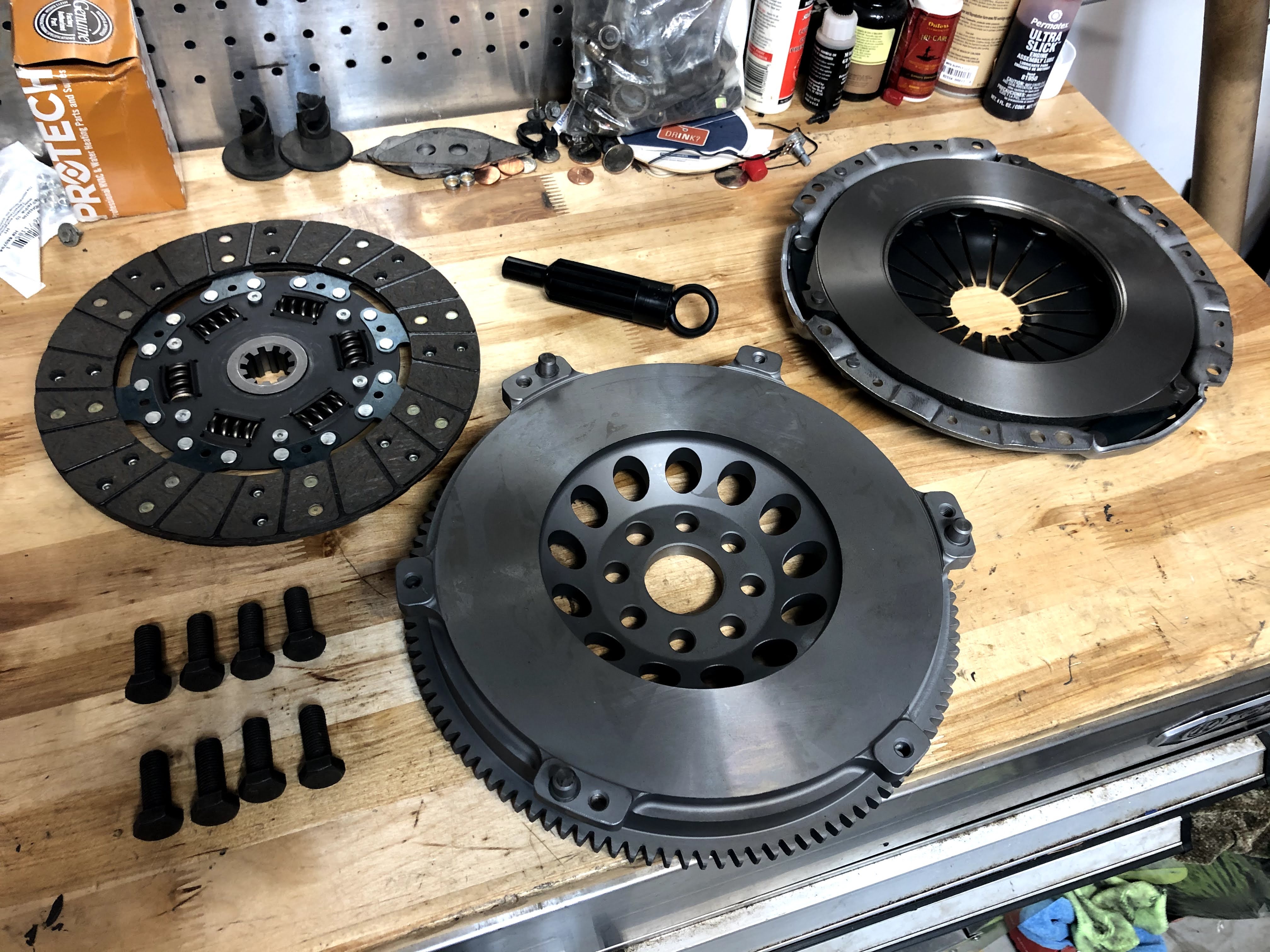
Out of the box, the kit looked really good and incredibly high quality for the price. I was honestly very surprised. Even the new flywheel bolts that it came with looked to be high quality.

Here’s a close-up picture of the actual clutch disc. It weighs 2 lbs, 15.1 oz.

Here’s a close-up picture of the forged chromoly flywheel, notice how it’s dished in the middle. This will come into play when fitting the clutch disc into position. It weighs 14 lbs, 5.6 oz. From what I’ve found, the stock dual-mass flywheel weighs around 25 lbs. This is over a 42% decrease in the flywheel’s rotating mass. It should make the engine rev faster and be more responsive.

Another picture of the clutch disc side of the flywheel.

Here’s a picture of the crankshaft mounting side of the flywheel. You can see the two holes where material has been removed in order to balance the flywheel.

Here’s a picture of the pressure plate, showing the clutch disc side. It weighs 11 lbs, 9.4 oz.

Here’s a picture of the side of the pressure plate that faces the throw-out bearing / transmission.

Before actually starting with the clutch install on my S52 engine, I first needed to remove the old rear main seal and pilot bearing. Always a good idea to remove these as a “while you’re in there” sort of job.
In the picture above, you can see that I’ve started prying out the brown rear main seal. I just used a normal seal puller. It came out really easily.

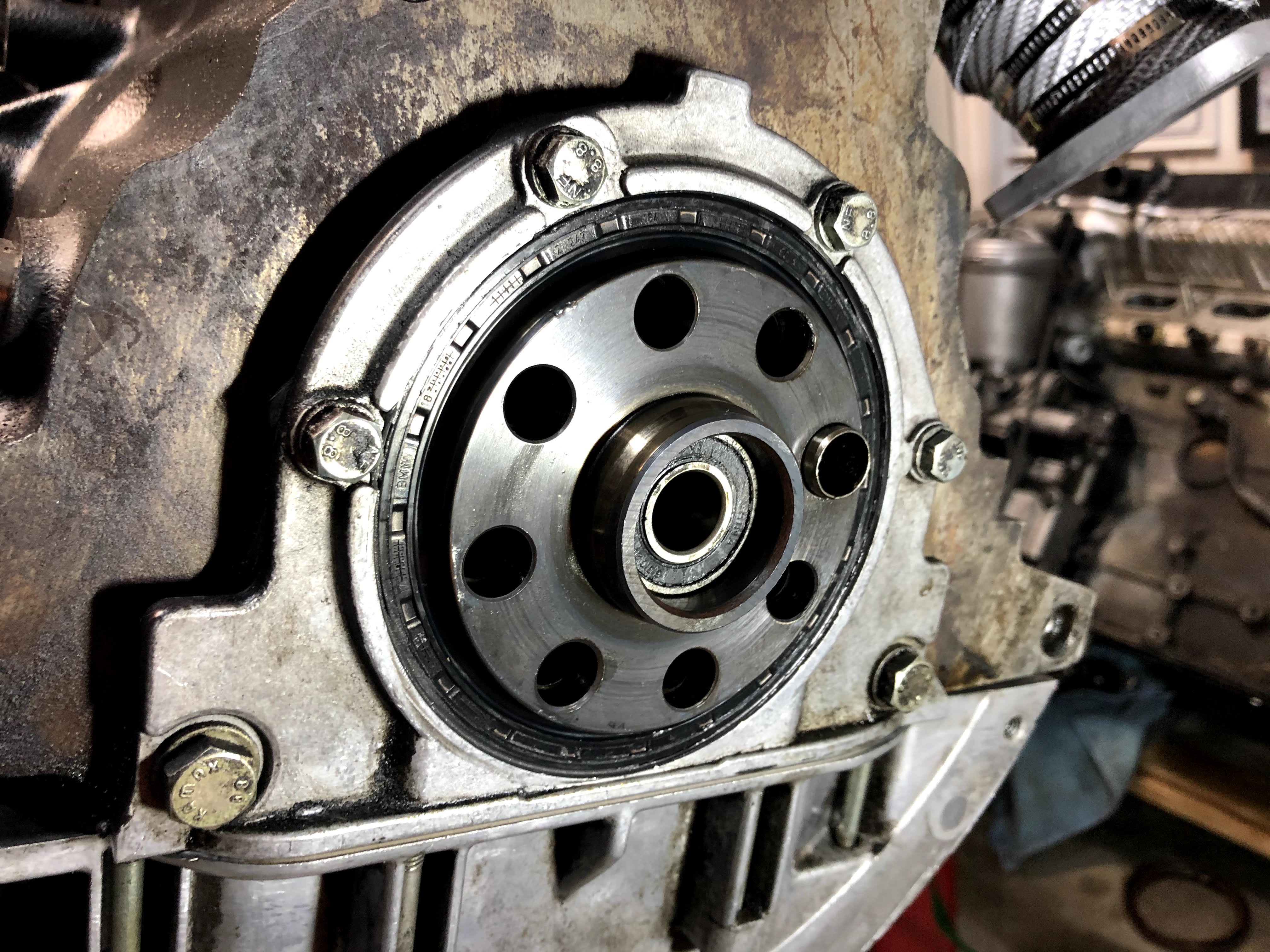
Here’s a picture of the same area after removal of the seal. The piece of metal with the eight holes in it is the back of the crankshaft where the flywheel mounts to. You can actually see the pilot bearing in this picture as well (circled in red).
The purpose of the pilot bearing is to support the transmission’s input shaft. The input shaft is what runs through the middle of the clutch assembly and transmits engine torque into the rest of the driveline.

Installing the rear main seal is very simple. The BMW OEM seal that I purchased included a white plastic cup that fit perfectly over the rear of the crankshaft. With the seal located by the cup, you then just need to slowly and gently knock it into place. I used a ratchet extension and a rubber mallet.
With the seal installed, it was time to remove and replace the pilot bearing. I tried to pull it out with my seal remover but it didn’t budge even a millimeter. Time to see what the masses on the internet had to say! After reading a bunch of ideas of how to remove it, I decided to turn to hydraulic pressure. Sounds scary but it’s incredibly simple!

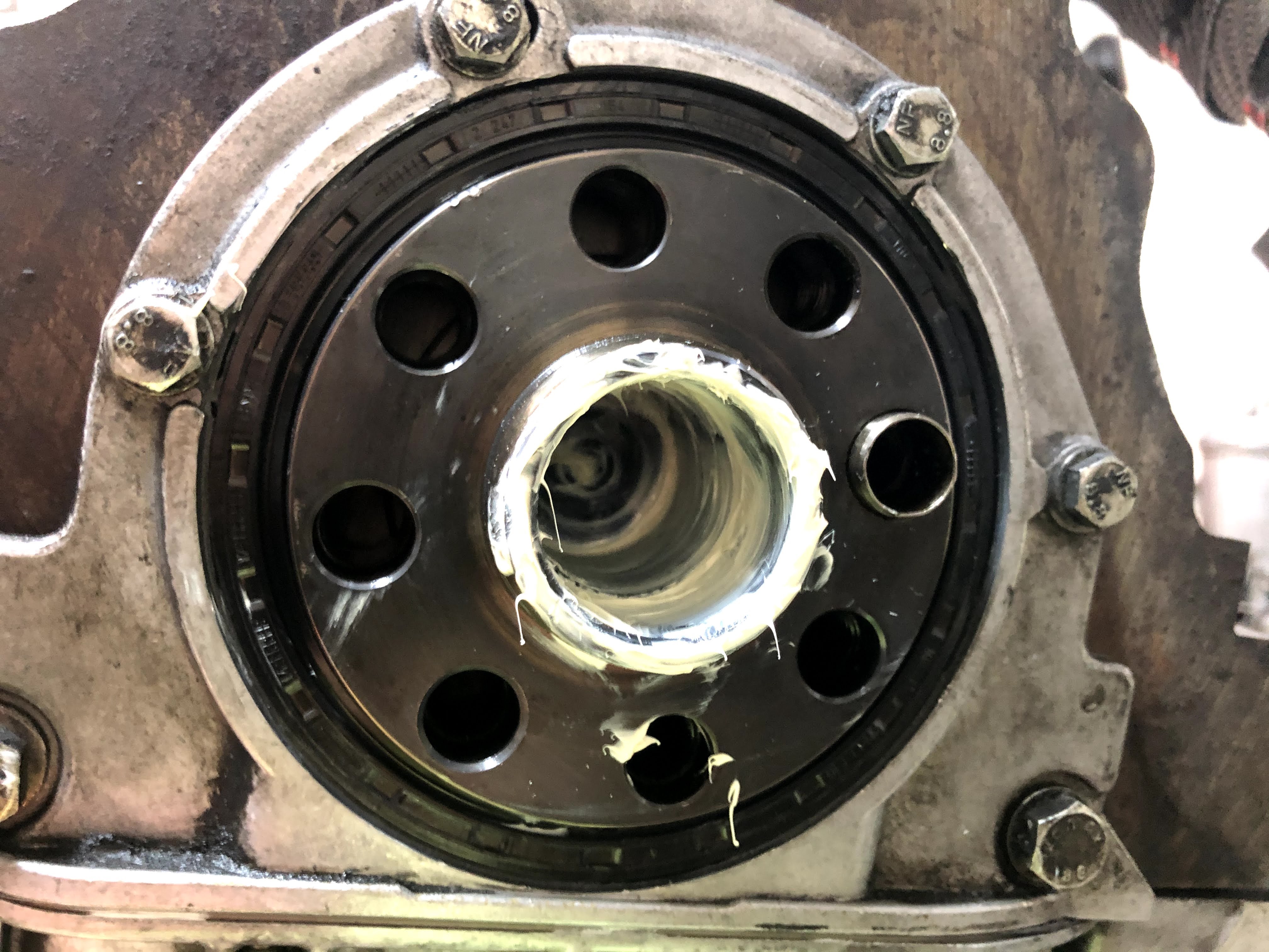
Step one is to cram as much grease as you can into the void behind the pilot bearing. Don’t worry, there’s basically a cup behind the bearing that will contain all the grease. The grease has nowhere to go. Just use your finger and push the grease through the middle of the bearing.

The next part sounds weird but it works. You need to find a wooden dowel, strong piece of plastic or a cylindrical piece of metal that has an outside diameter that’s close to the inner diameter of the pilot bearing. After measuring, I determined that the pilot bearing ID was 0.55″. After searching around the garage, I found a drill bit with an OD of 0.50″. I thought this would be close enough. In the picture above you can see that I’m using the rear of the drill bit, not the drill portion.

Now, you’re going to whack the piece of whatever you choose pretty decently with a hammer. The physics of what’s actually happening is that you’re displacing the hydraulic fluid (grease) with your bit/dowel and the only place it has to go is on the inner surface of the pilot bearing. That puts a lot of pressure on the pilot bearing and simply pops it right out!

One hit with the hammer and I could easily pull it out the rest of the way with my pinky finger.
Here’s a picture of the area right behind the pilot bearing.
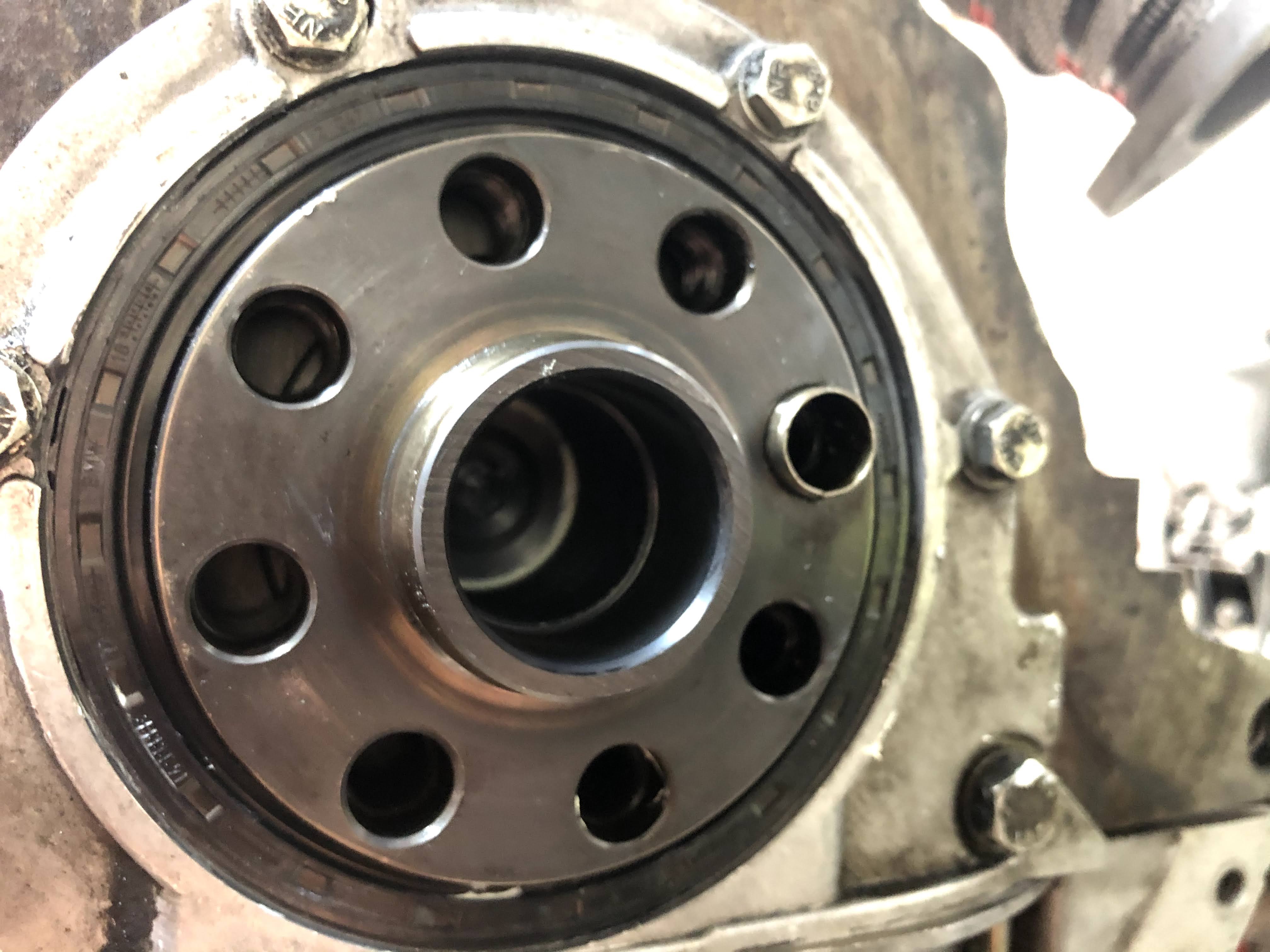
And here’s another picture with it completely clean again. No big deal! You can also see the small raised lip inside the hollow area where the pilot bearing is indexed against. This way you can’t push the new bearing in too far.

I left my new pilot bearing in the freezer overnight to slightly reduce its size and make installation a little easier. In the picture above I’ve just set it in place.
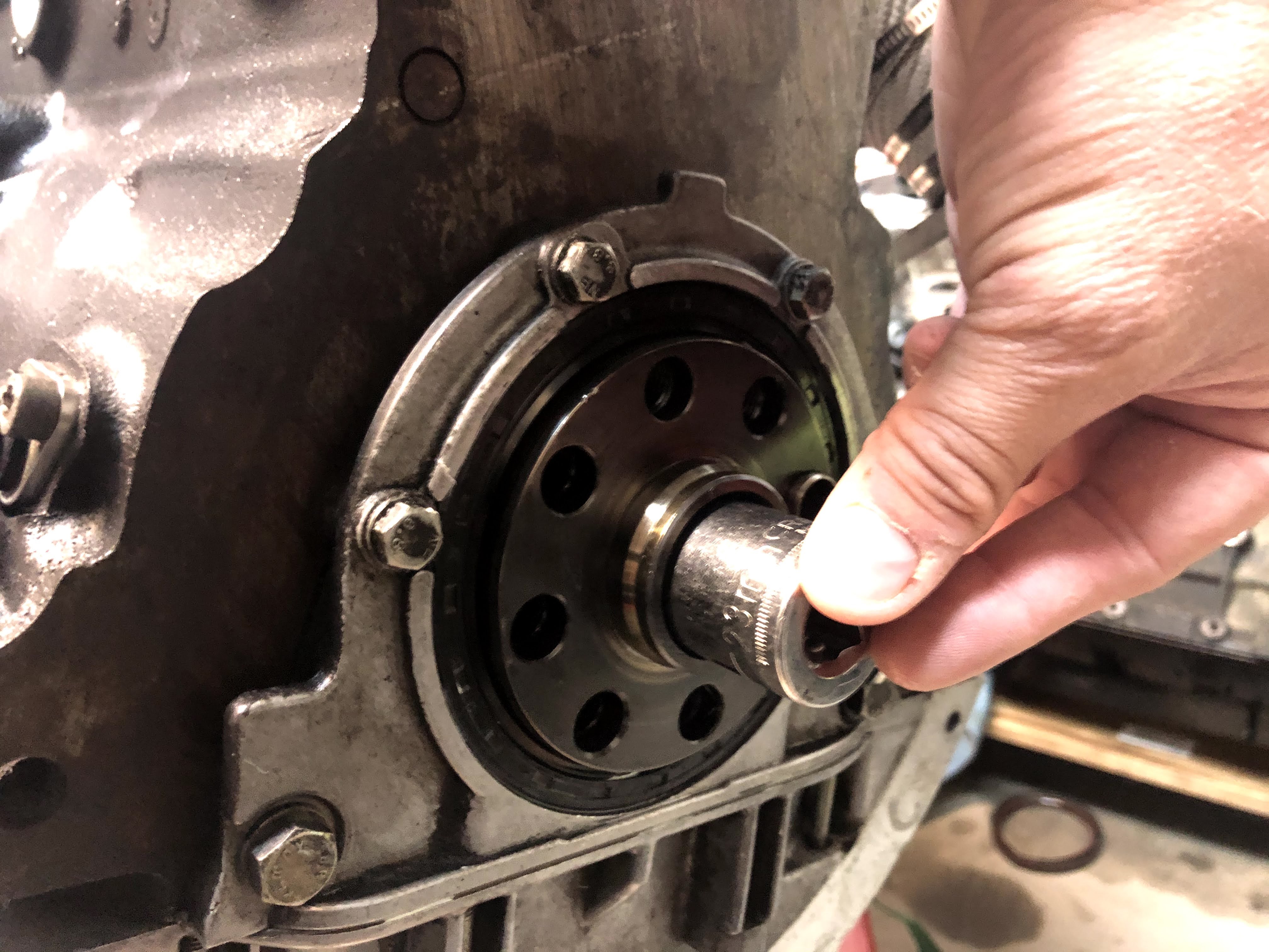
I then found a socket that just barely fit inside the hole where the pilot bearing installs. For me, that was a 23mm socket. Gently knock it into place with your rubber mallet.

Installed!

Time to finally install the actual clutch assembly. Step one is to bolt the flywheel to the crank extension with the eight bolts included in the kit. I snugged up each bolt lightly by hand to make sure that the flywheel was seated correctly. I then proceeded to snug up each of the eight bolts, using a star pattern, to 25 Nm. I then snugged them all up to 40 Nm in a start pattern and noticed that I wouldn’t be able to go to the final torque setting of 105 Nm without locking the flywheel in place.
It looked like I could simply fabricate a piece of steel to lock the flywheel in place via the locating dowel and a transmission mounting bolt. You can see the piece of steel installed on the flywheel in the picture above. I put a slight wave in the piece so I could have more threads of the transmission mounting bolt threaded into the block. The lock worked perfectly and I was able to torque all the bolts to spec.
I then made sure to thoroughly clean the face of the flywheel with brake cleaner. It’s crucial to get the surface clean with no remaining residue left.

Time to finally place the clutch disc into location against the flywheel. It seems like quite a few people have managed to install clutch discs backwards and even the instructions in a lot of kits can lead to the disc being installed in the wrong orientation. The issue is that one side of the clutch disc protrudes out further because it contains the spring pack. You can see the “spring pack side” in the picture above (with the mounting tool in place).

Most forums stated, that with the FX racing kits, you need to place the spring pack side towards the flywheel. When I set the clutch disc in place in that orientation, I could tell that the spring pack fit in the flywheel pocket with plenty of clearance in every direction. It was clear that this was the proper orientation.

The clutch was now sitting in place, held very well in the proper location by the black plastic clutch install tool that was impressively clearanced to the ID of the pilot bearing.

The next step was to install the pressure plate. Unfortunately, the kit didn’t include the necessary socket cap screws to complete the job. A quick search on Amazon found the necessary M8-1.25 x 16mm high grade steel screws.
I used brake cleaner to thoroughly clean the surface of the pressure plate that will contact the clutch disc. I then set the pressure plate onto the three locating dowels of the flywheel and hand installed the socket cap screws with blue Loctite applied to the threads.
It’s critical to slowly and evenly tighten the socket cap screws to pull the pressure plate against the clutch disc. The pressure plate will initially be pushed away from the clutch disc by the spring fingers in the plate. As you tighten the socket cap screws, you’re compressing the springs and pulling the pressure plate towards the flywheel. I tightened in a star pattern and went around about 5 or 6 times so that only slightly more torque was being applied each time. The final torque applied to each screw was 34 Nm.

In the picture above, you can see the clutch disc sandwiched between the flywheel and the pressure plate. The final torque has been applied to the socket head screws in the picture.

Above you can see the locating dowel on the right side with the socket head screw on the left side.

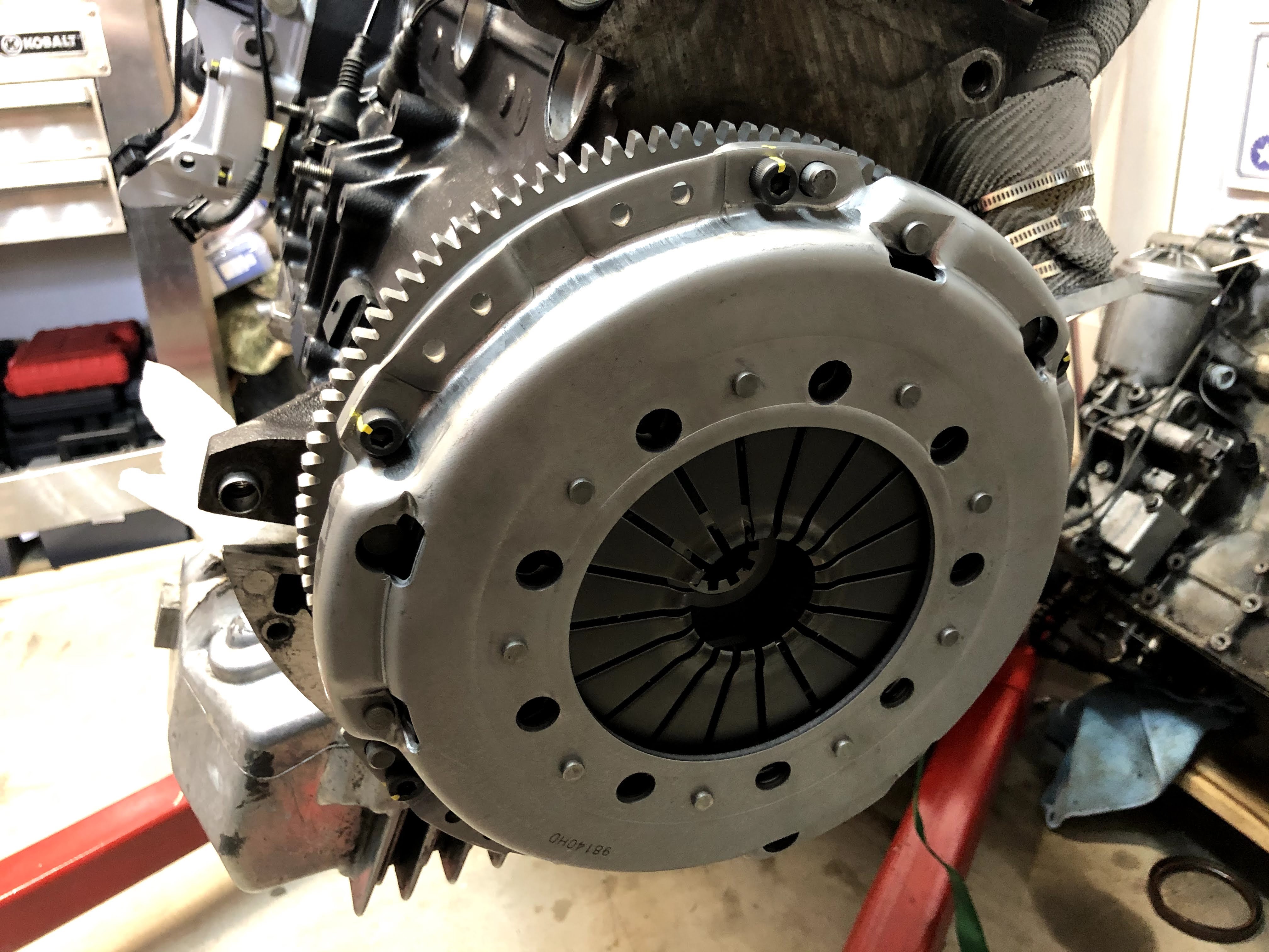
The clutch assembly is now fully installed on the engine. In the picture above, you can see how the 10 splines of the transmission input shaft will slide into the clutch disc and then into the pilot bearing. Looking good! Hopefully the transmission lasts!

Now to move to the transmission side of the clutch replacement. In the picture above, you can see the front of the throw out bearing riding on the splined transmission input shaft (with the pivot fork behind it). Let’s dig in deeper.

The first thing that I had to do was remove the pivot fork and throw out bearing so that I could get to the pivot pin and guide tube.

Take a look at this OEM style plastic pivot pin! The entire top of it had disintegrated and it was literally crumbling. I don’t know how much more life it had in it before complete failure.

Definitely a good time to move to the Rogue Engineering stainless steel pivot pin (lightly greased). I’ve heard of issues with the brass pivot pin so I just went all the way to the stainless steel version.

The guide tube that was installed had also seen better days. It was so worn by the throwout bearing that there were physical grooves cut into the sides of the tube. Good thing I had a new one ready to go.

I also decided to spring for a high quality throwout bearing, Sachs. Here’s a look at the Sachs Performance Heavy Duty throwout bearing compared to the Chinese made one that came in the clutch kit. There were actually very few visible physical differences but it’s the details in the materials used and bearing specs/quality that are important.

The transmission input shaft seal actually looked really good with no visible signs of an issue, so I left it in place.

All that was left to do was to install all the new components (with a very light grease on the transmission input shaft and guide tube). Ready to mate the engine to the transmission!
UPDATE:
I’ve put about 125 miles on the clutch and everything is working fine so far! The first 500 miles are supposed to be break-in miles for the clutch disc. I’ve been taking it relatively easy and been trying to change gears frequently with very few full throttle applications. I’ll keep updating this page as I get more miles on the clutch.
If you liked the information in this page, be sure to check out my Developments page for my most recent posts! Every single post is listed with a link on the Headquarters page.
Links:
Pressure Plate Socket Cap Screws

Terrific article especially for an individual that on several of the same cars you are working on. Coincidentally as I have just moved to a new location in La Quinta California my car ended up at a BMW dealer. I have no concerns as to the quality of workmanship and equipment but I certainly am well aware that the price I will be paying will be higher than the one you complete it. I checked on her and no the parts are available most likely from the same manufactures that do it private label and then event due to the limited amount of supercharged E 36 M Coupes I appreciate your effort in putting the story out .Mark / MR Z3
LikeLike
Mark, I’m glad you’re enjoying the posts and finding them informative. I put these posts out there for the community as I know that I would’ve found them helpful when undertaking each project myself.
LikeLike
Awesome write up. Did you apply lock tite to the flywheel bolts or was that unnecessary? Planning to do this soon on my 97 E36 M3/4/5. I’ve heard i need maximum clearance under the car to do it. Did you do the job on jackstands?
LikeLike
Benjamin, I applied blue loctite but you could also apply orange if you’d like. I was able to do it with my car just on jackstands but remember that I installed the clutch on the engine with it sitting on a stand. The transmission was left in the car. So I had to install the engine and mount it to the transmission at the same time. Most people would remove the transmission from the car to mount a new clutch to the engine. Good luck!
LikeLike
Thank you for putting together these writeups. This one in particular and the supercharger install have been really helpful for me. Cheers.
LikeLike
Justin, glad to hear that you’re finding these helpful. I just really want to help out the global E36 community with what I’ve learned when wrenching on my car.
LikeLike
can someone tell me the type and the exact length of the screws for the flywheel?! I have lost the screws, and those from the stock flywheel are too long 😦
LikeLike