
Now that the my Vortech supercharged 3.2L S52 engine has been successfully installed in my E36, I need to address some supporting systems in order to make it perform reliably on the track. After discussing my build with a few other veteran BMW E36 racers, they really voiced their concerns about keeping the intake air temperature at a manageable level when out on a road course racetrack (not autocross).
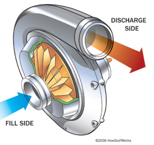
The issue is that a supercharger works by compressing air and the side effect of that is dramatically increased charged air temperature. The Racingcalcs website actually has an easy to use calculator that states 9psi boost pressure from a centrifugal supercharger will result in ~100*F temperature increase over ambient:
https://racingcalcs.com/supercharger-boost-temperature-calculator/
The reason that increased air temperature is a concern is that it will lead to detonation in the combustion chamber. An S52 engine has two knock sensors that detect when detonation begins and it then retards timing to save the engine. This would most likely result in power less than even stock levels in a heavily retarded situation. The good thing is that we can address the increased charge air temperature in a couple different ways.

The most commonly used way to reduce the temperature of the charged air is by using an intercooler (either air-to-air or air-to-water). However, due to very tight spaces on the intake side of the S52 engine (also applies to the M50 / S50 / M52), it’s quite difficult to fit the necessary piping for an intercooler. Race Marque Systems (RMS) is the only company that I know of that has managed to cram in an air-to-water intercooler between the supercharger outlet and the throttle body. In the picture above, you can see where the intercooler resides. What you can’t see are the coolant lines running from it to a small dedicated radiator in the front of the car. This is a similar intercooler/aftercooler setup to what BMW uses with their S55 engine (though that charge air cooler is much larger).
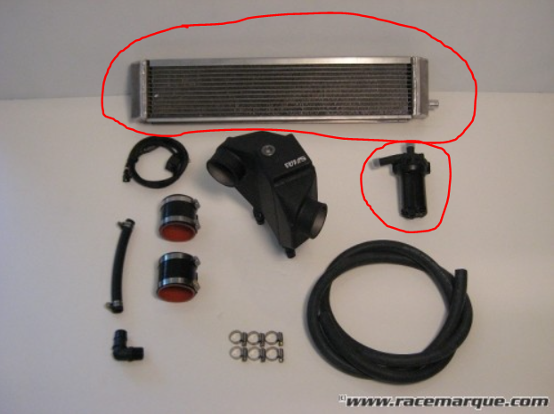
The nice thing about the RMS system is that you can increase the size of the radiator and dedicated coolant pump for even more cooling capacity. However, the system comes at a considerable price tag. For that reason, and the complexity in installation, I’ve decided to go a different route (at least initially).
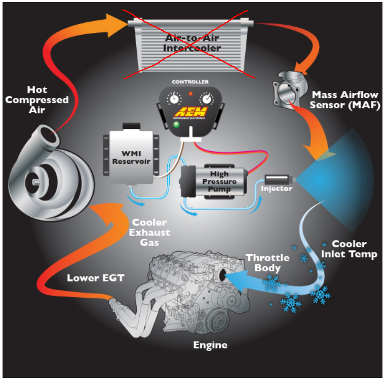
The second most popular method of cooling an engine’s charge air is chemical intercooling. And the most popular type of chemical intercooling is Water Methanol Injection (WMI). With WMI, you’re injecting a highly atomized mist of a solution of water and methanol (usually a 50:50 ratio), via a nozzle placed in the charge pipe, that absorbs heat (water) and increases octane rating (methanol). The combination can reduce the charge air temperature by 100*F. The picture above, from AEM, demonstrates the main parts of a WMI system (I won’t be using the air-to-air intercooler that they have depicted).
It’s interesting to note that even Race Marque Systems has built customer cars using a Water Methanol Injection system coupled with their charge air cooler:
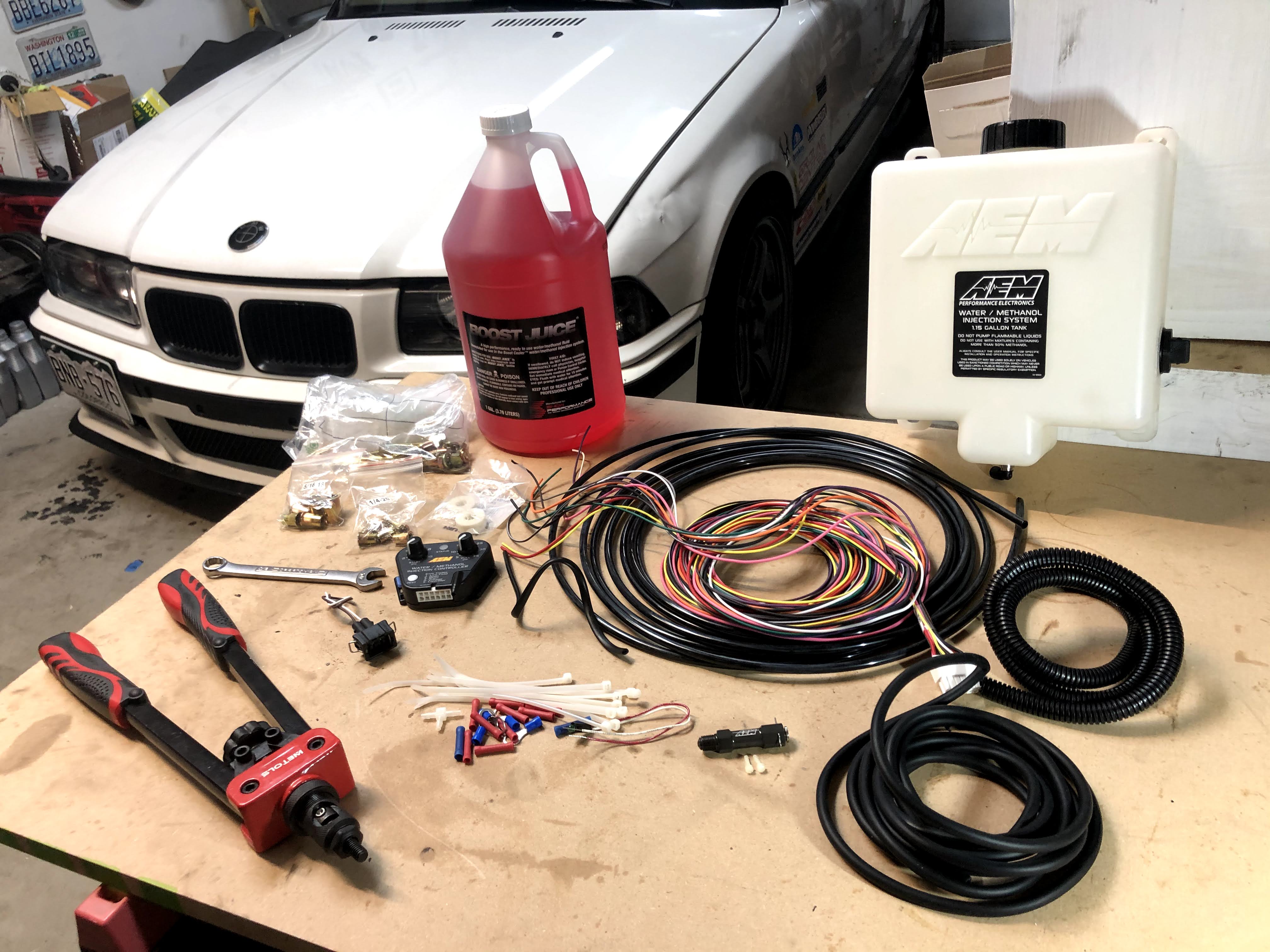
After researching a few different WMI options, I decided to go with the AEM kit (p/n 30-3300, V3 version) as it was an impressively complete system, with an outstanding injection nozzle, and very simple controller setup. The picture above is what I received in the kit (but without the pump pictured as I had already installed it prior to this picture). I highly recommend taking a look at the official AEM video overview of the kit and their interesting test setup that shows the V3 nozzle improvements:
The basics of the AEM kit are pretty simple:
- Tank to hold the water/methanol solution
- Electric pump to get the solution from the tank to the nozzle at the front of the car
- Filter to make sure no debris makes it to the nozzle (not part of the official kit but an option that I added)
- Nozzle, installed in the charge air pipe, to distribute the solution into the intake air
- Controller to moderate the flow from the pump, based on the boost pressure
Let’s take a look at a few of the specific parts of the kit.
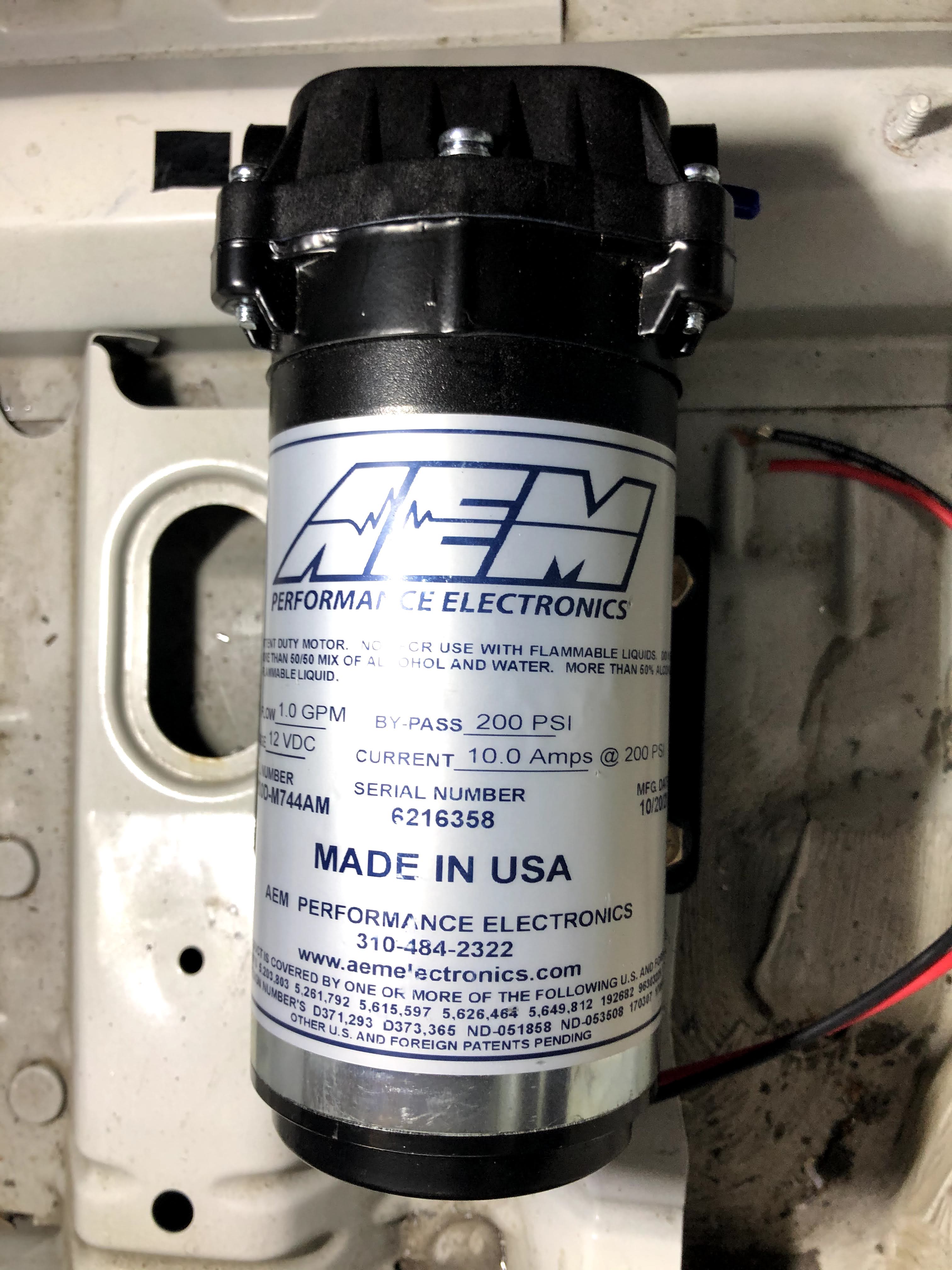
High pressure, by-pass pump, with very smooth and quiet operation. It doesn’t actually cycle on and off, it runs continuously when the car’s on.
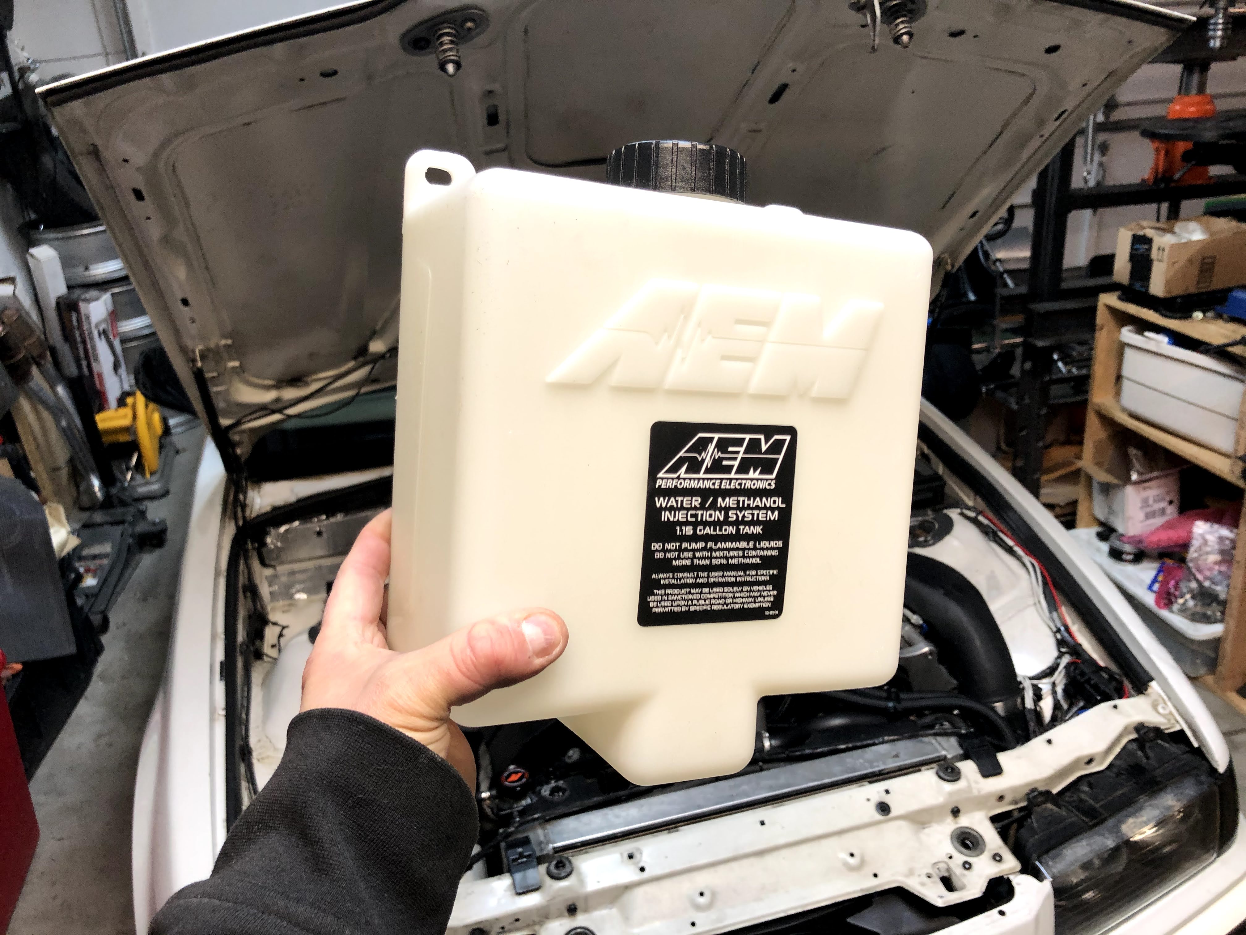
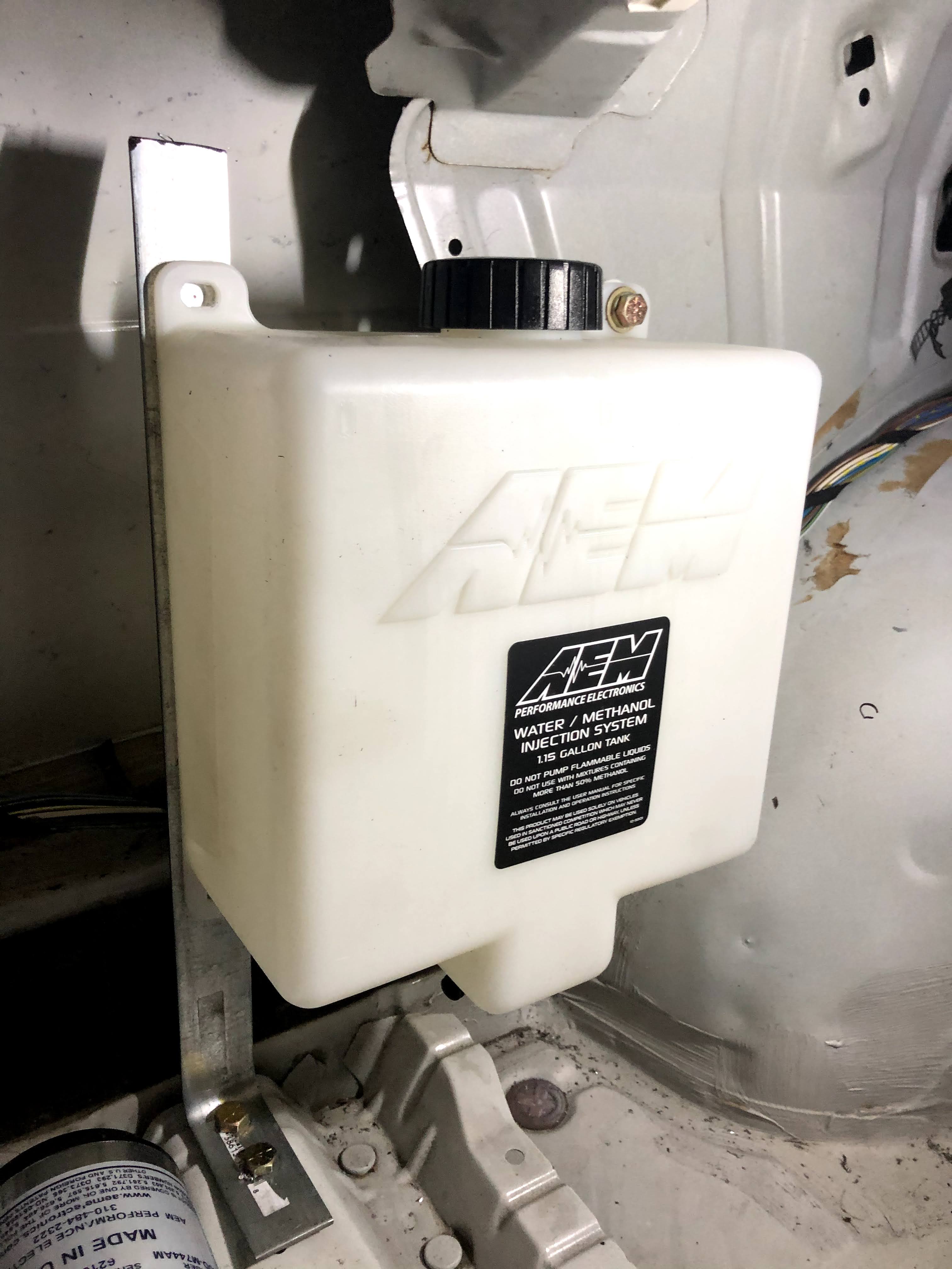
1.15 gallon tank with a clever design at the bottom in order to keep the pump fed until nearly all the solution is gone.
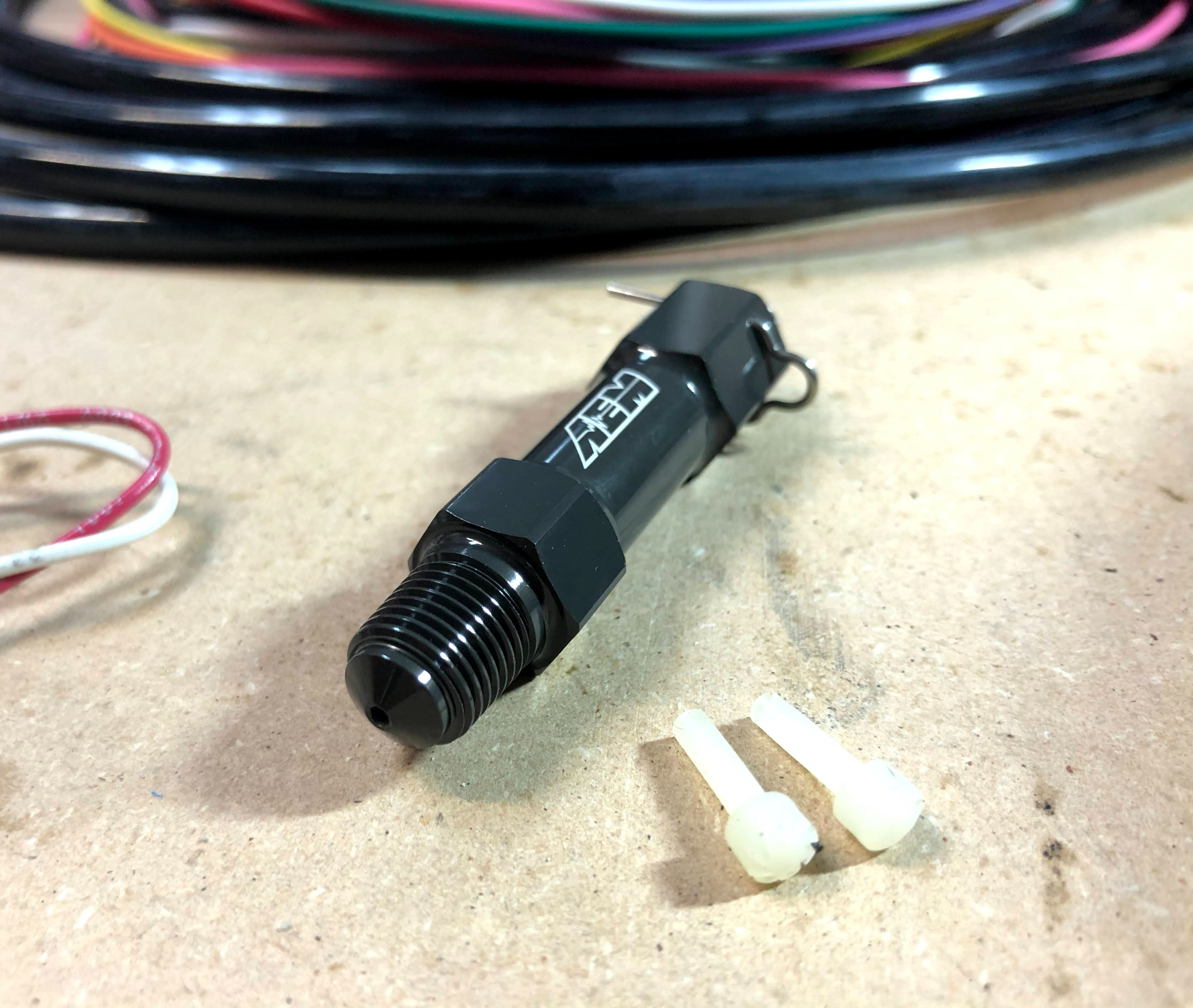
V3 injection nozzle with a couple different flow volume restrictors.
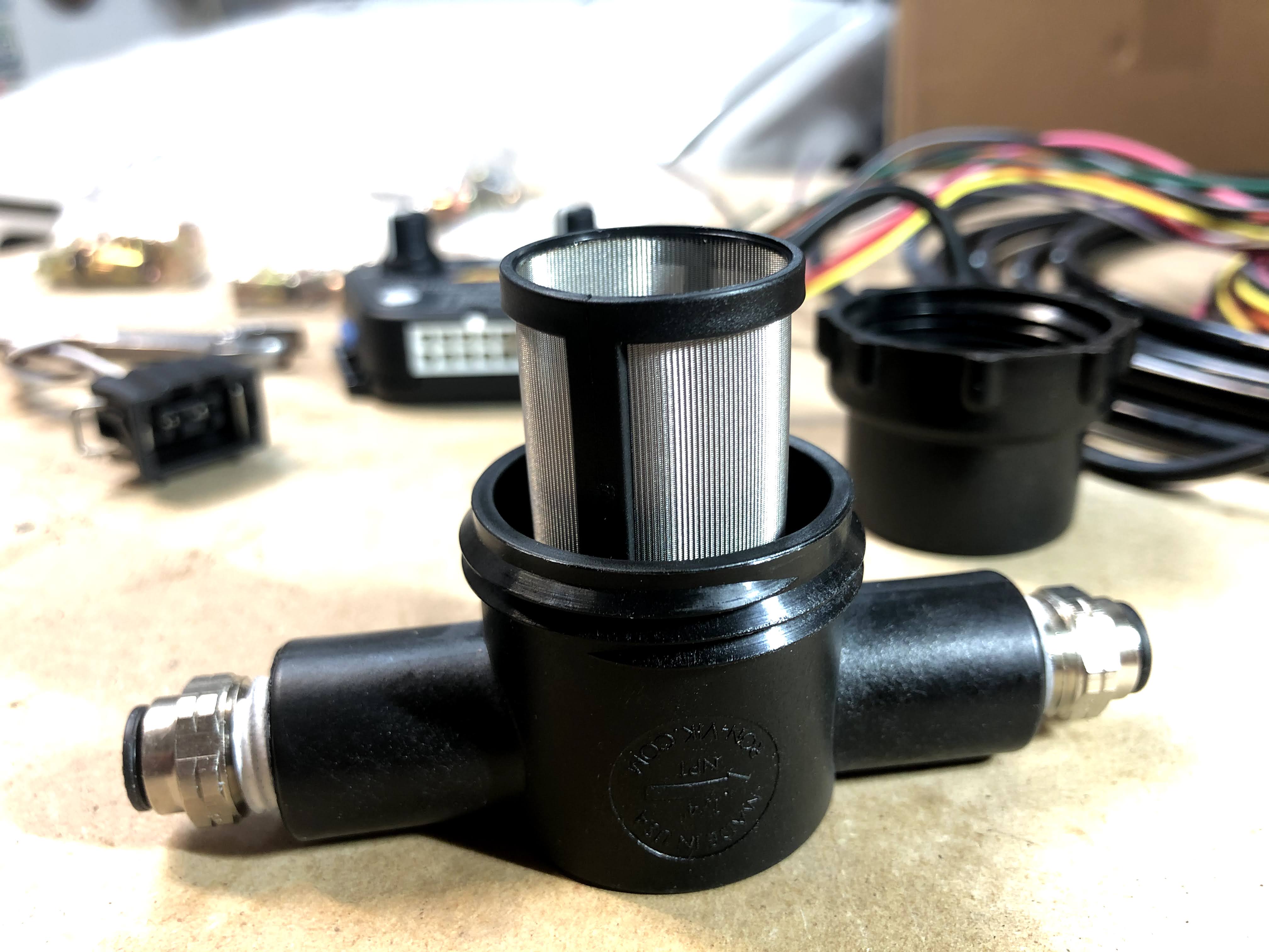
Filter canister with the cap off so that you can see the screen. I purchased the filter separately, it’s not included with the kit.
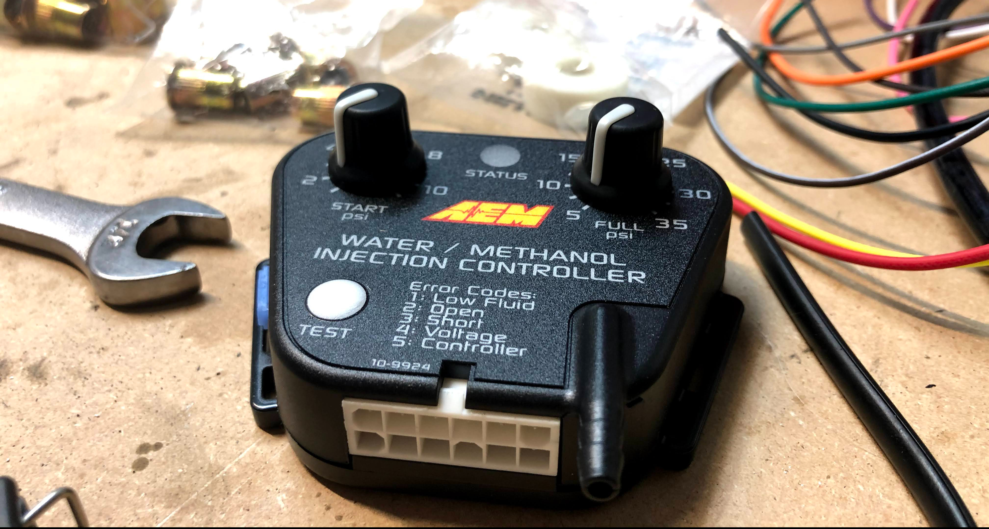
Controller with boost reference nozzle. You can see the two dials that set at what boost level you want the WMI to start and when you want it to be at full flow. The flow increases linearly between the “start” and “full” settings.
The first step when installing the AEM kit is to determine where to mount the tank and pump. Luckily, with a stripped interior, I just had to go searching in the back of the car for some suitable locations. I discussed possible locations with a fellow BMW E36 enthusiast, Phillip S., as he had just recently installed the same kit. His setup looked great and so I used it for inspiration for my own setup.
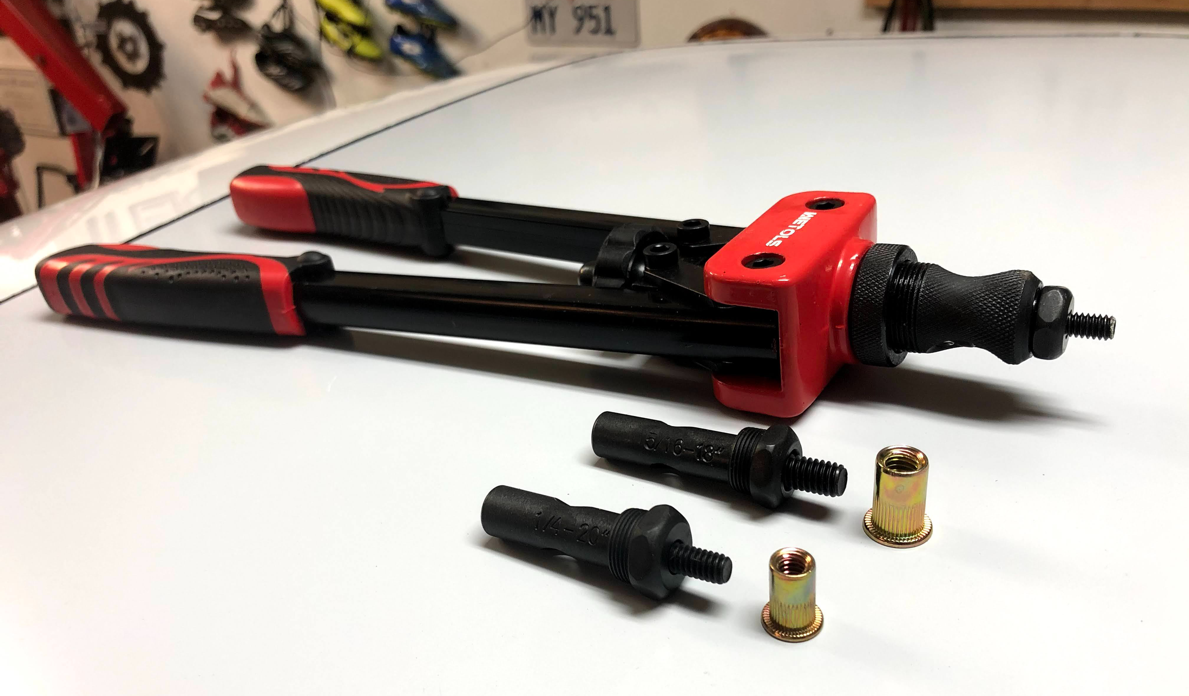
I think it’s very important to solidly mount the pump and tank in the car as they’ll be subjected to a lot of varying loads when racing. Nut-serts looked to be the best mounting method. Take a look at the picture above of the low priced nut-sert (aka rivet nut) tool that I purchased on Amazon.
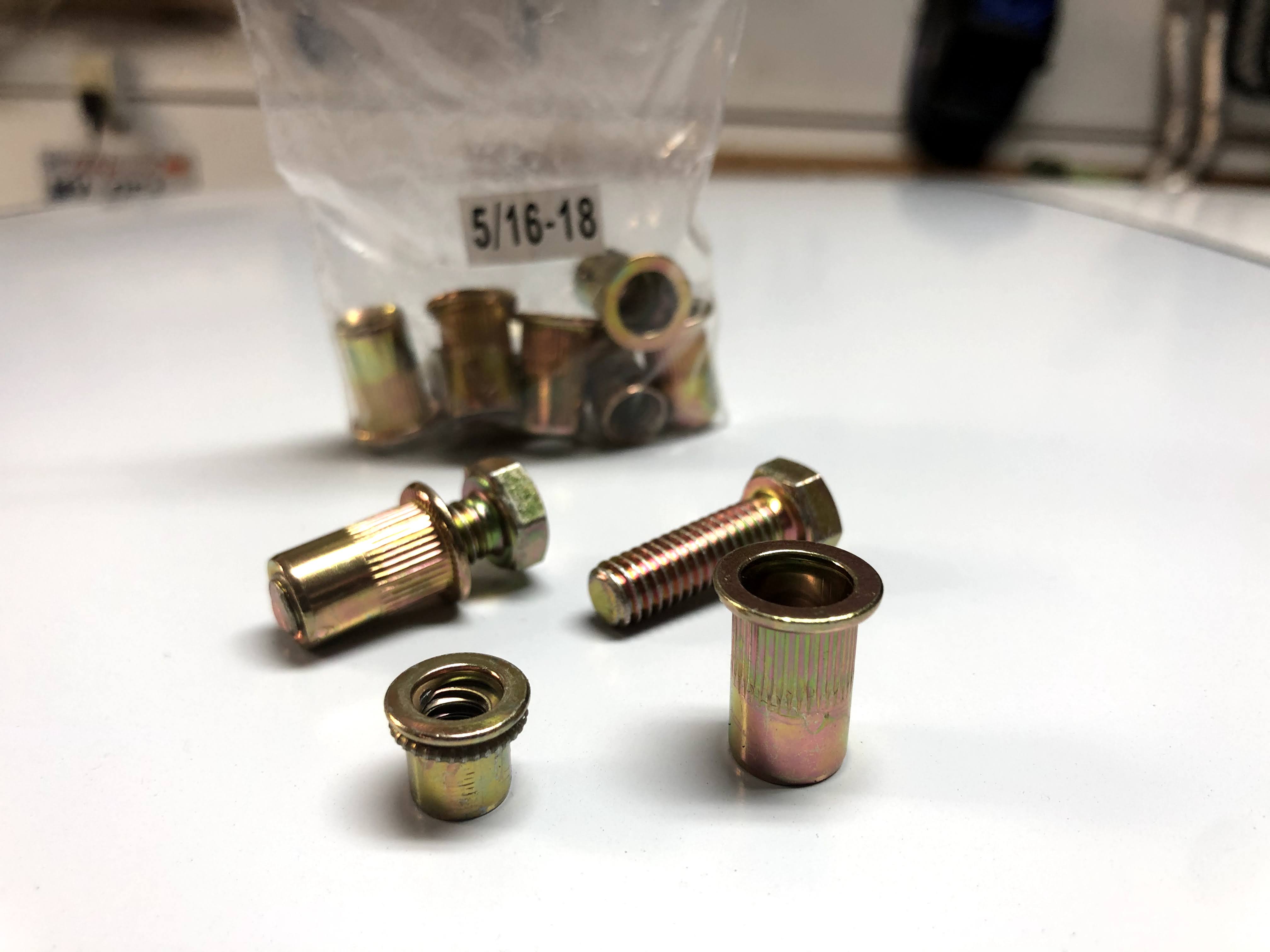
Nut-serts are threaded inserts that can blindly be installed into sheetmetal so that you can secure something with a bolt (and no nut on the back side). The picture above shows the nutsert in it’s uninstalled form (on the right) and what happens to it when you use the nut-sert tool on it (on the left). It basically creates a rear flange that sandwiches the sheetmetal with the front flange. Simple but very effective.
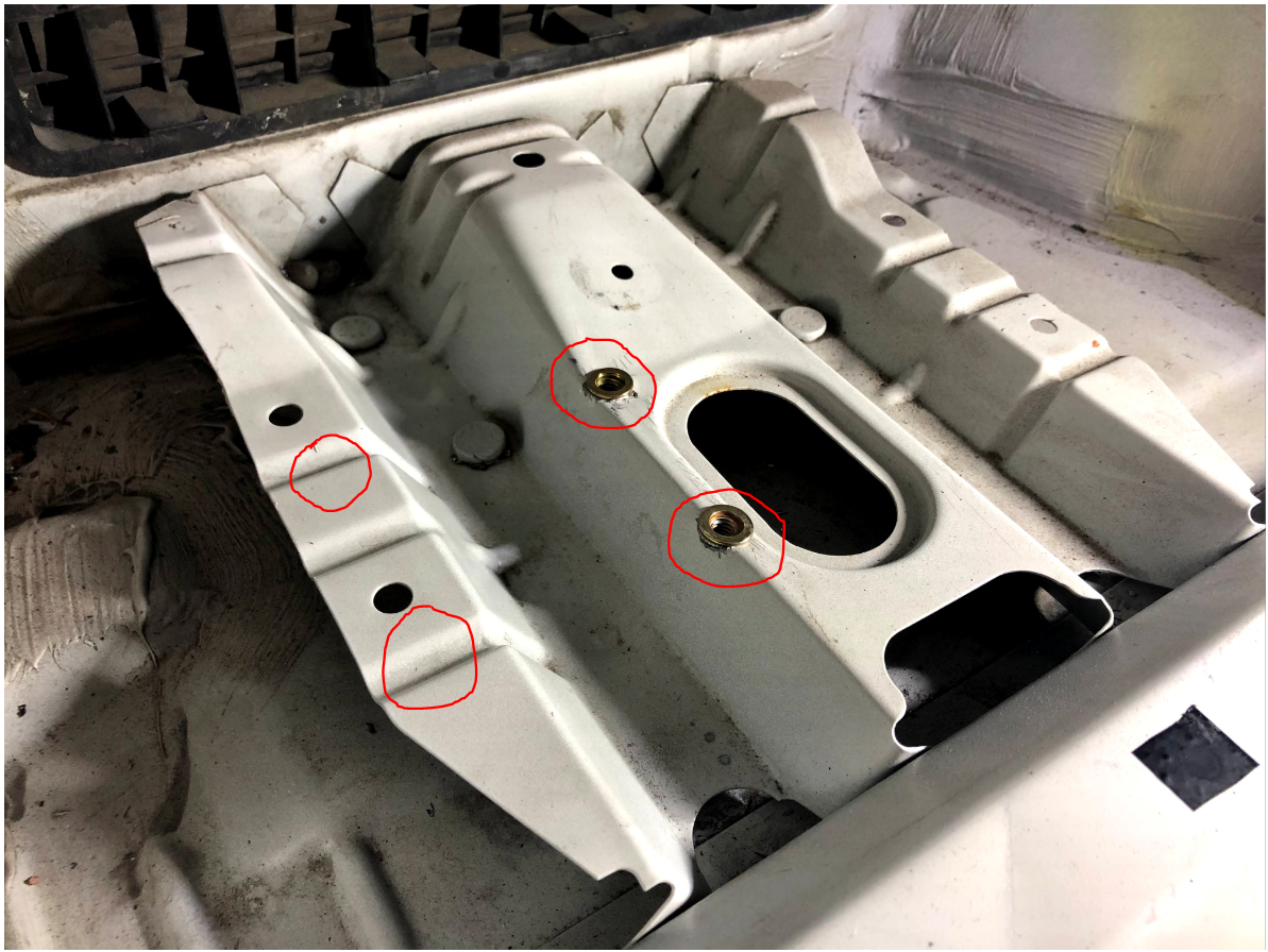
I chose the pictured area of the rear left trunk area to mount the tank. You can see that I have two nut-serts already installed. I installed two more nutserts in the other red circled areas. Just use the pump mounting points as a template.
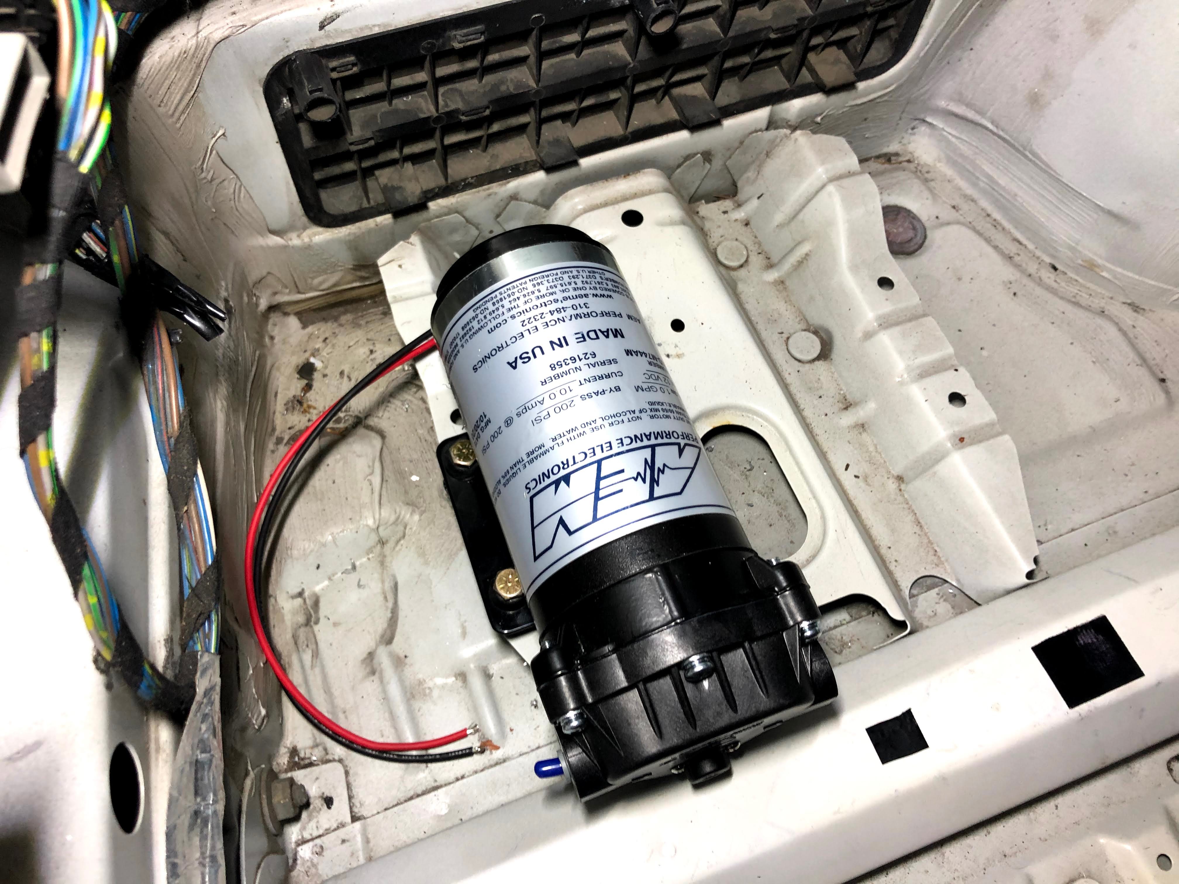
The pump uses rubber isolating feet, with holes in the middle of them, so that 1/4″ bolts can be threaded through to secure it to a bracket.
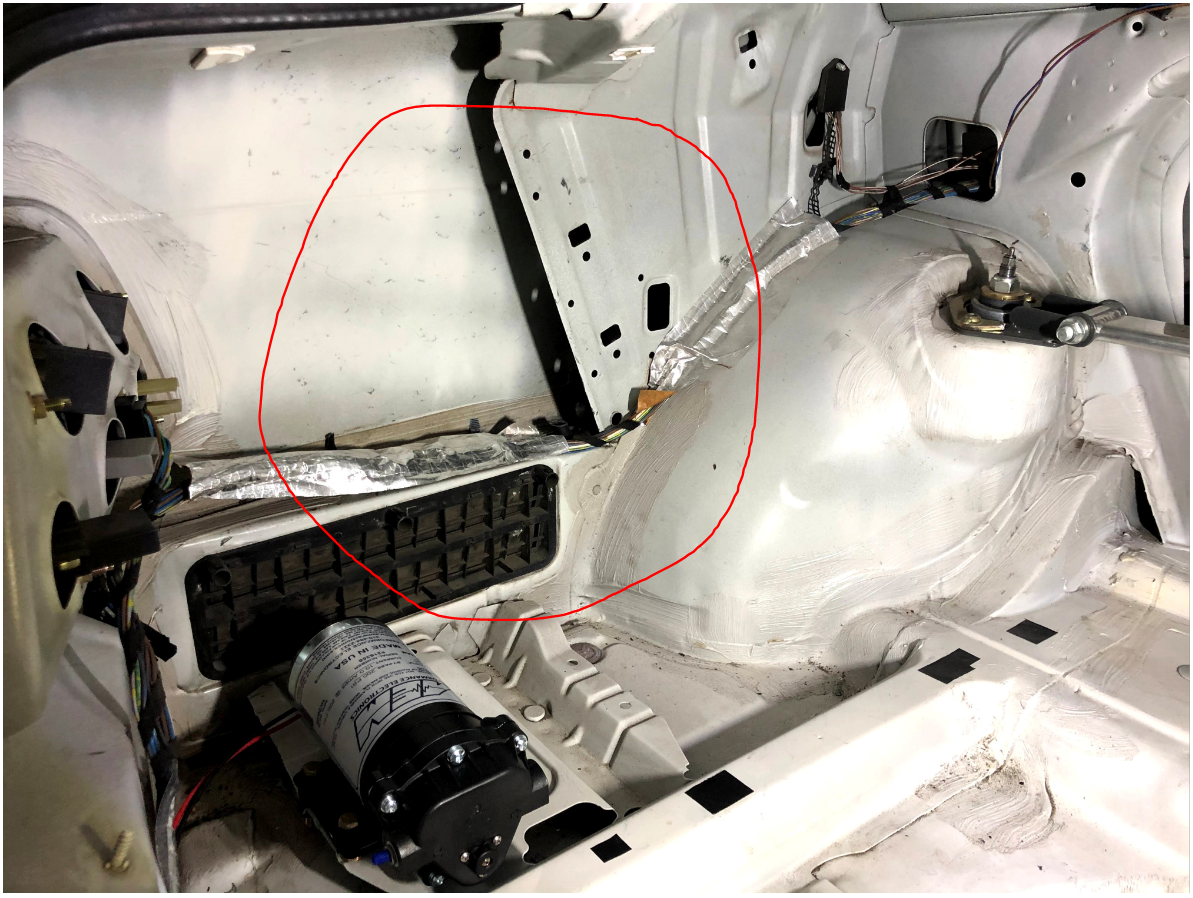
With the pump now securely mounted, time to pick out the best location for the tank. AEM says that the tank outlet should be mounted higher than the pump inlet. The red circled area in the picture above looks to be a great place but definitely provides a little challenge to find spots for all four tank mounting locations.
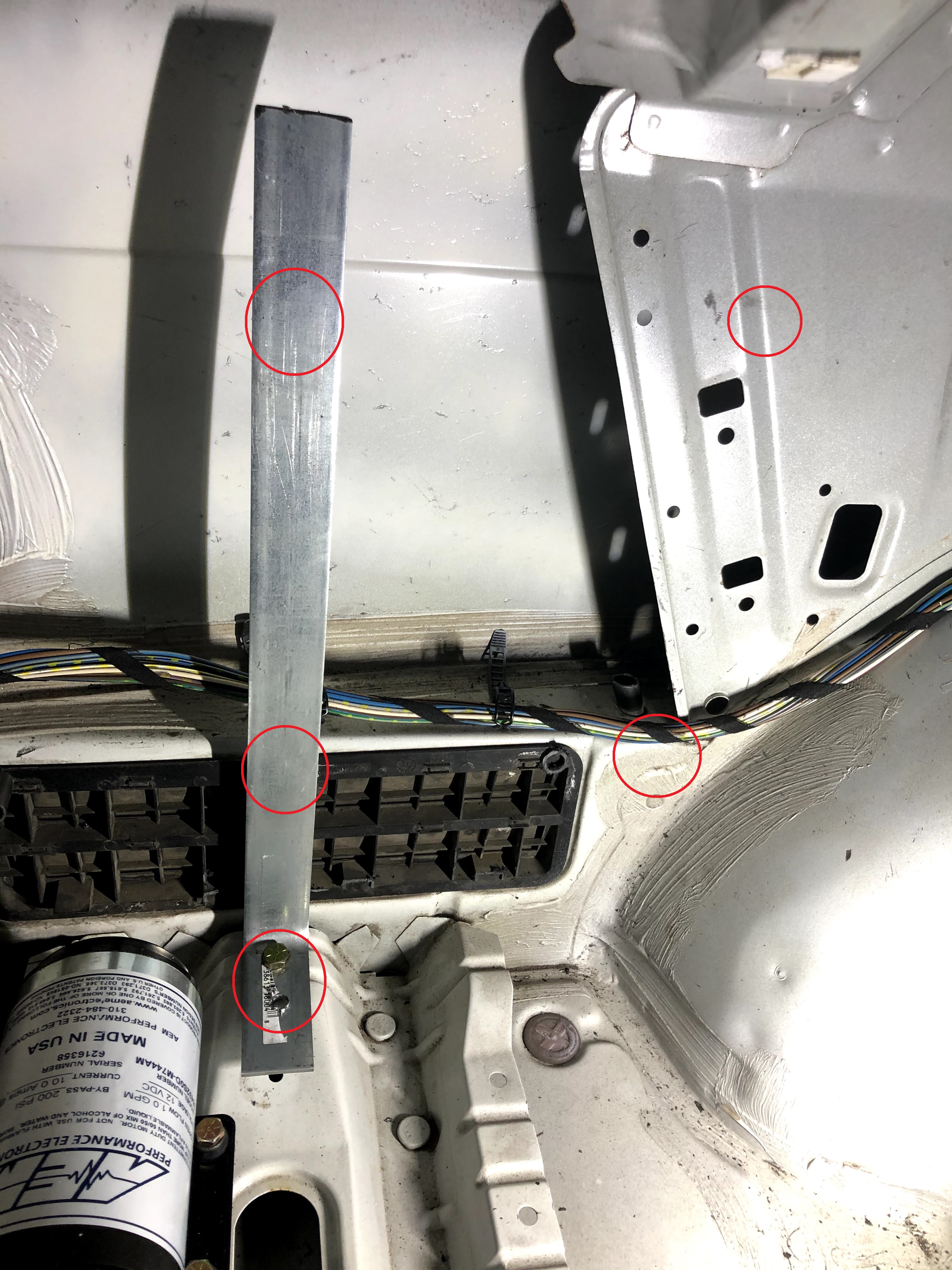
I decided that I could utilize the same floor bracket for some of the mounting and so I used a 12 gauge piece of galvanized steel, bent in a “L”, where two of the mounts would be located. I’ve circled all the areas where I in ended up installing nut-serts (5/16″ size).
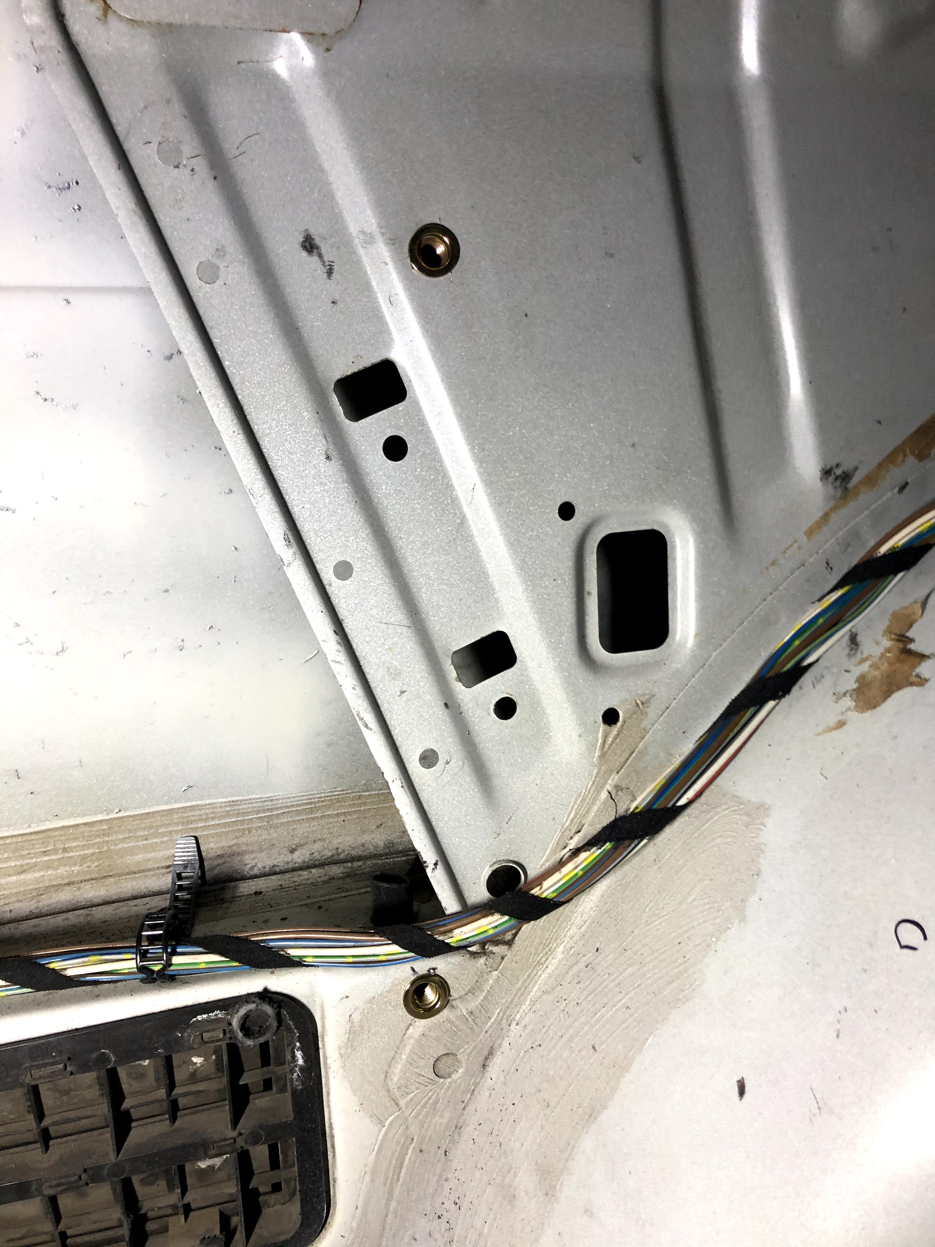
The other two mounts lined up nicely on some interior sheetmetal panels.
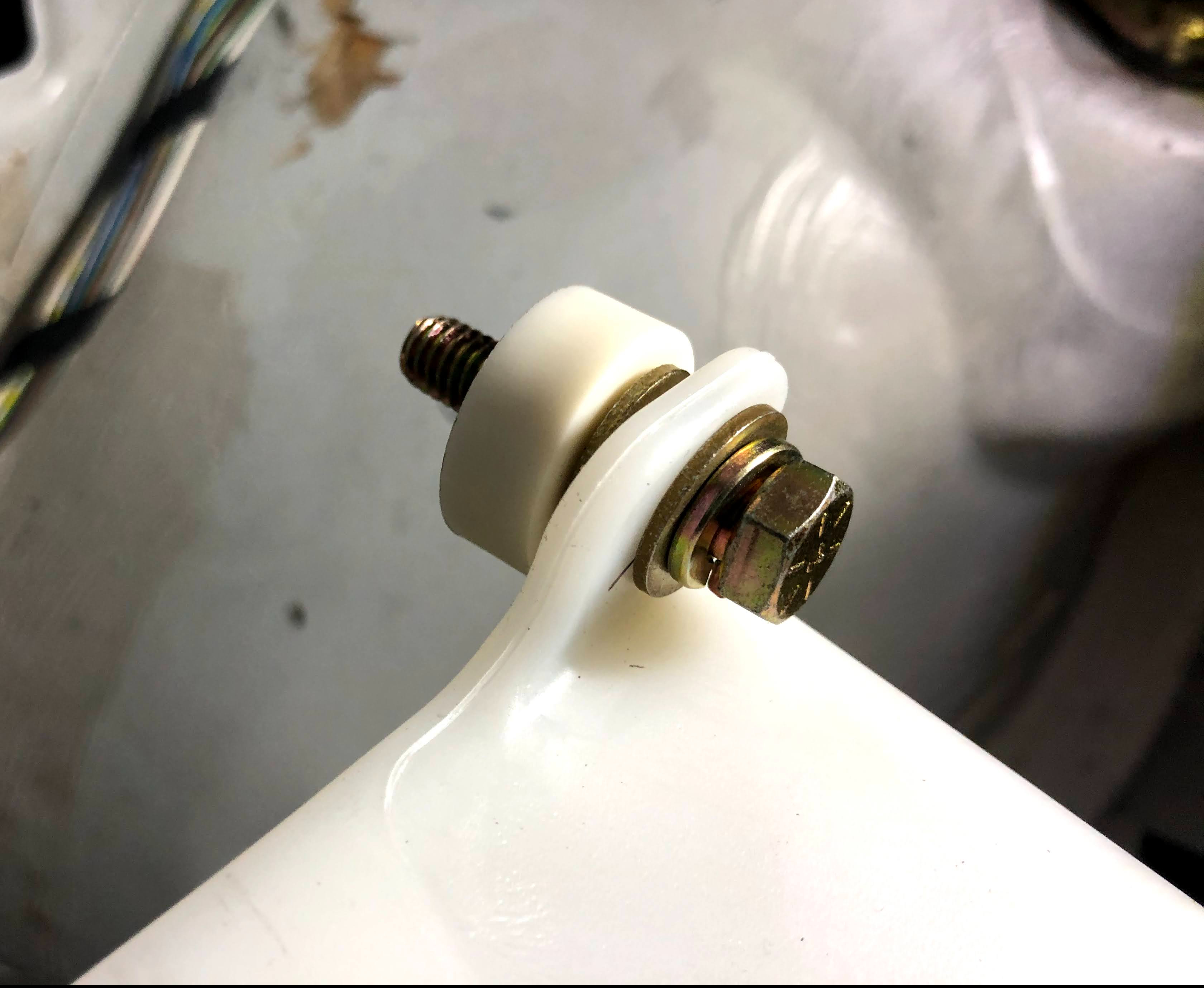
In order to provide enough clearance from some protrusions in the sheetmetal, I had to use nylon isolators when installing the tank (as pictured above).
With the bolts installed on the right side of the tank, I could then mark the location for the nut-serts on the steel “L” bracket on the left side.
The tank and pump where now both very securely mounted. Time to mount the filter and run all the wiring from the front of the car to the back.
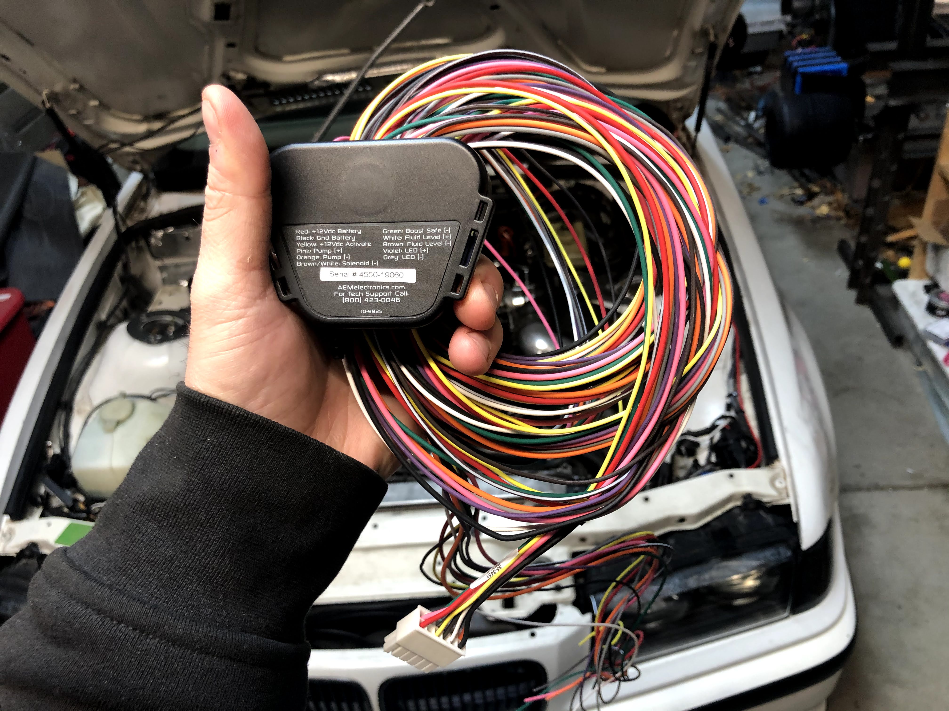
Pictured above is the back of the AEM controller which specifies which wire goes where.
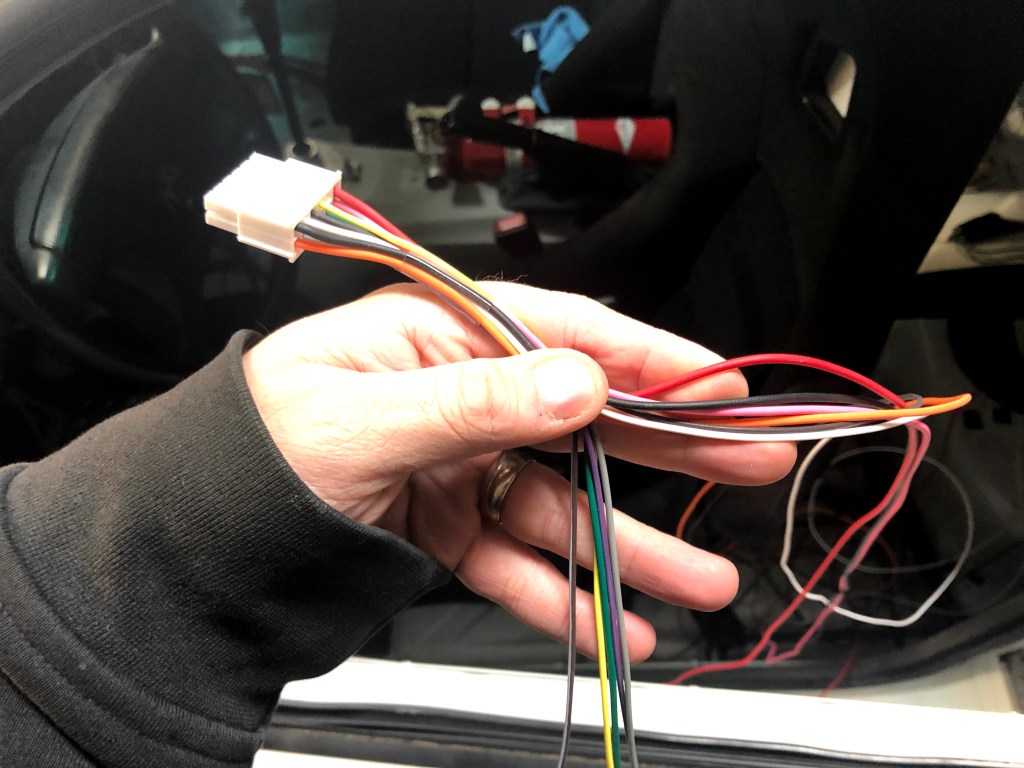
It ends up that you need to send about half the wires to the back of the car (heading right in the picture above), while the other half will head under the dash.
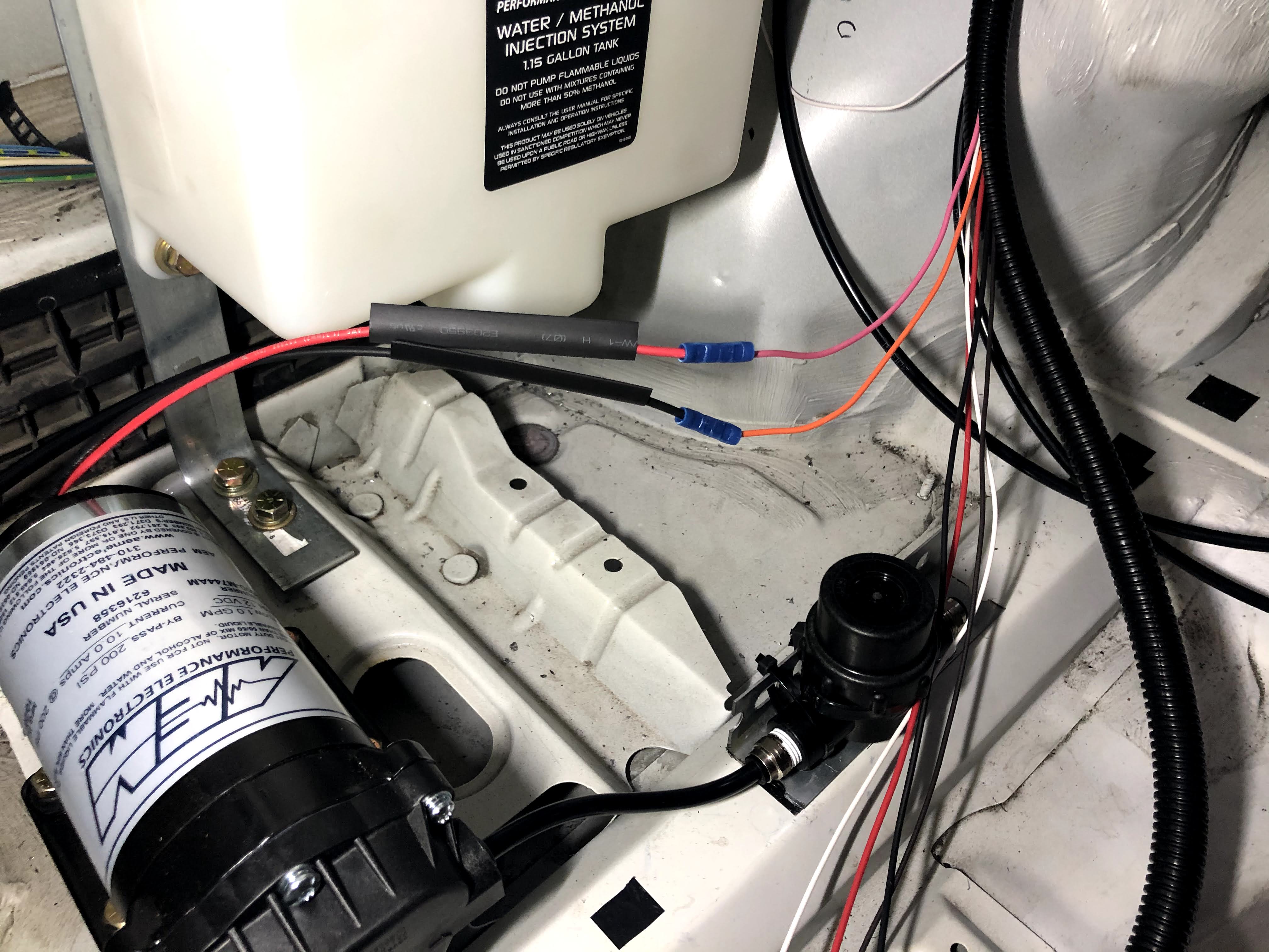
I found a great location for the AEM filter on the frame rail, created a small “L” bracket, and attached the bracket to the car with a couple sheetmetal screws. Then I just had to splice a bunch of wires (per the AEM diagram) and run the wires to the front of the car in a flexible plastic split conduit for protection. You’ll also need to run the actual injection tubing between the tank, pump, filter and to the front of the car as well.
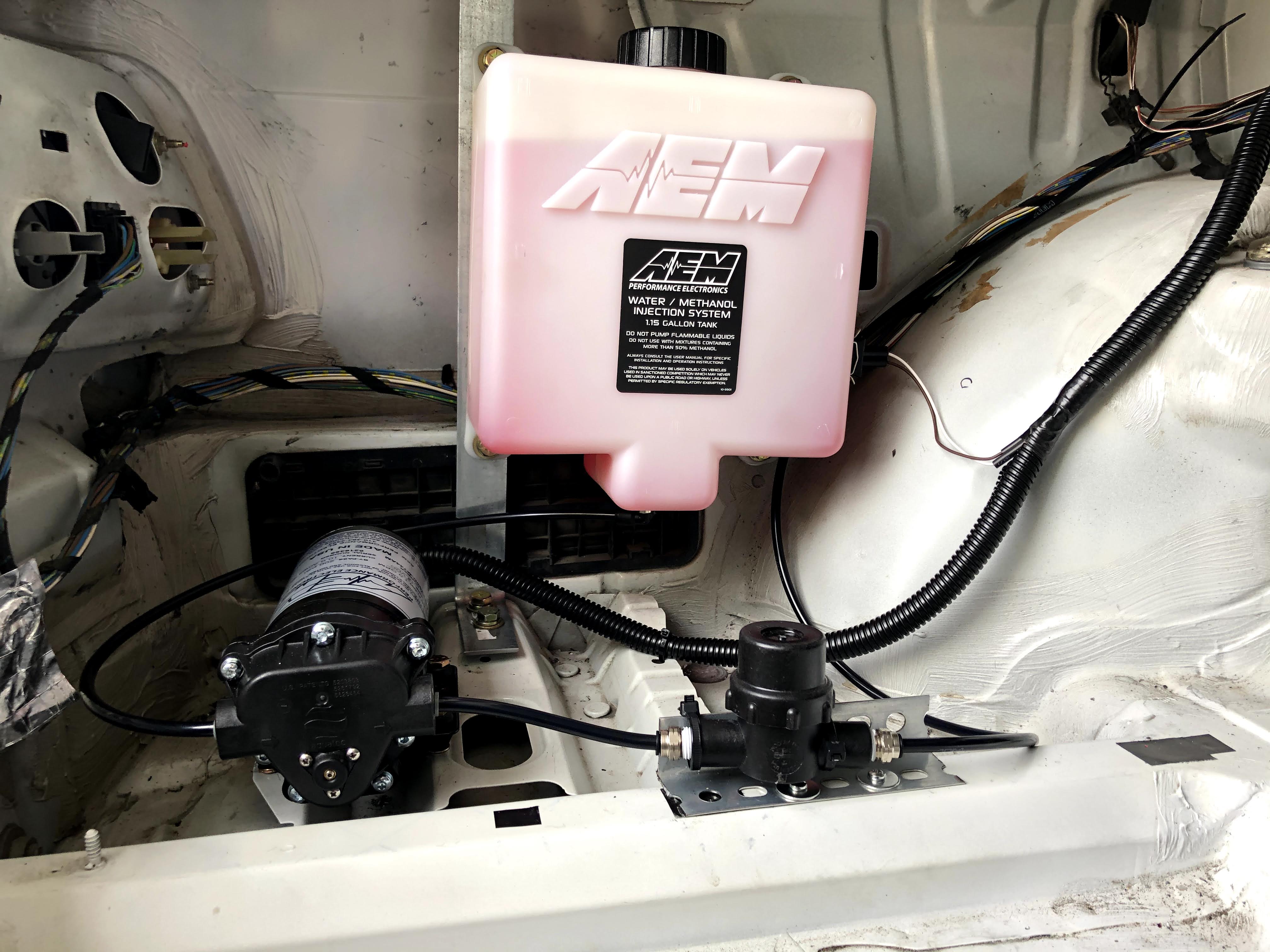
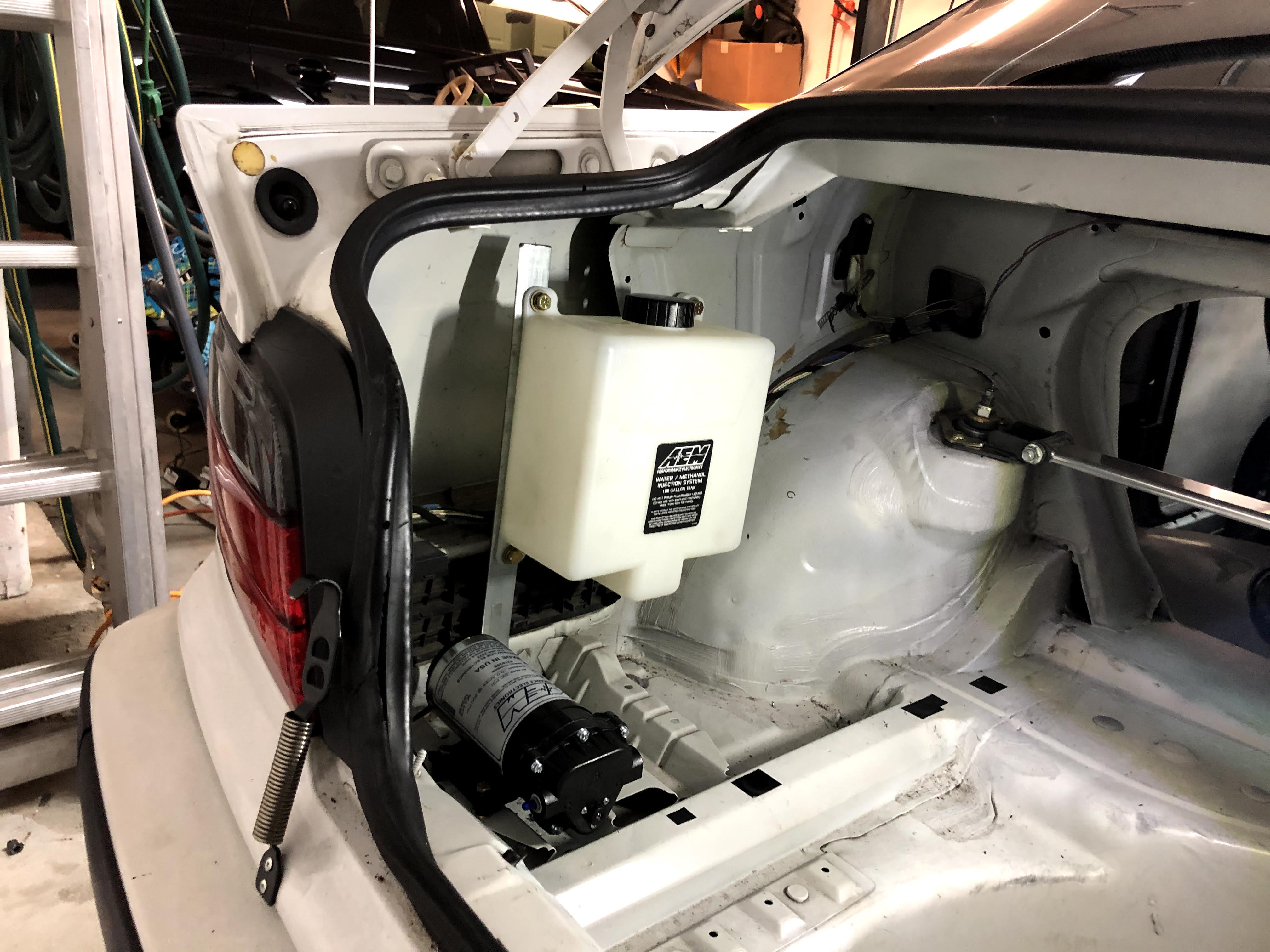
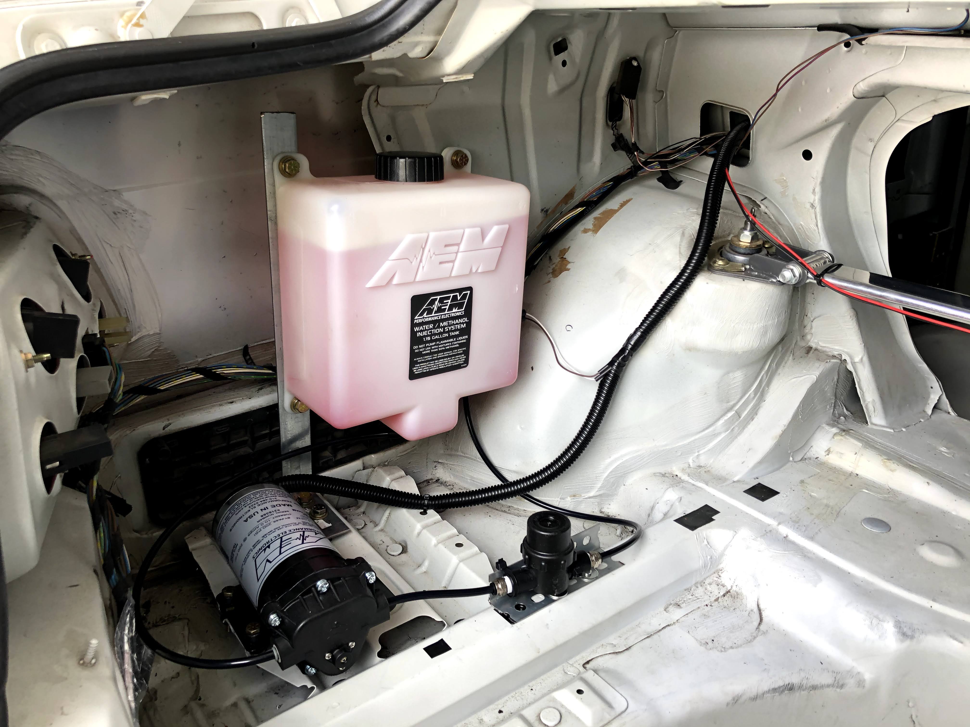
And here’s a picture of the final setup in the rear!
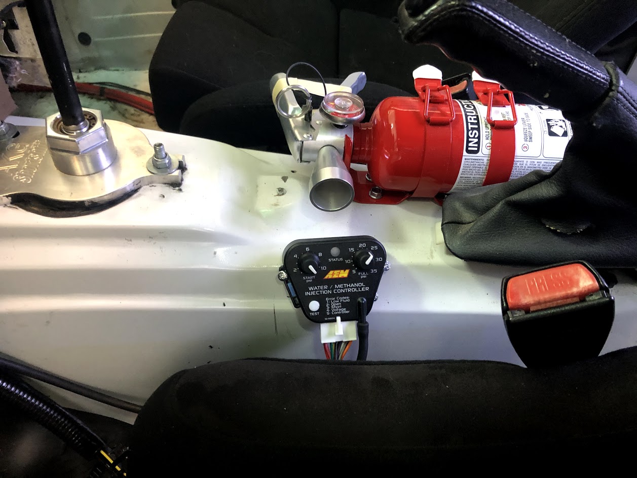
I mounted the AEM controller on the transmission tunnel, with some sheetmetal screws, where it’s within easy reach but still out of the way. You’ll need to run a few wires under the dash per the AEM diagram. Get to splicing and soldering! Finally time to jump into the engine bay and get the nozzle mounted.
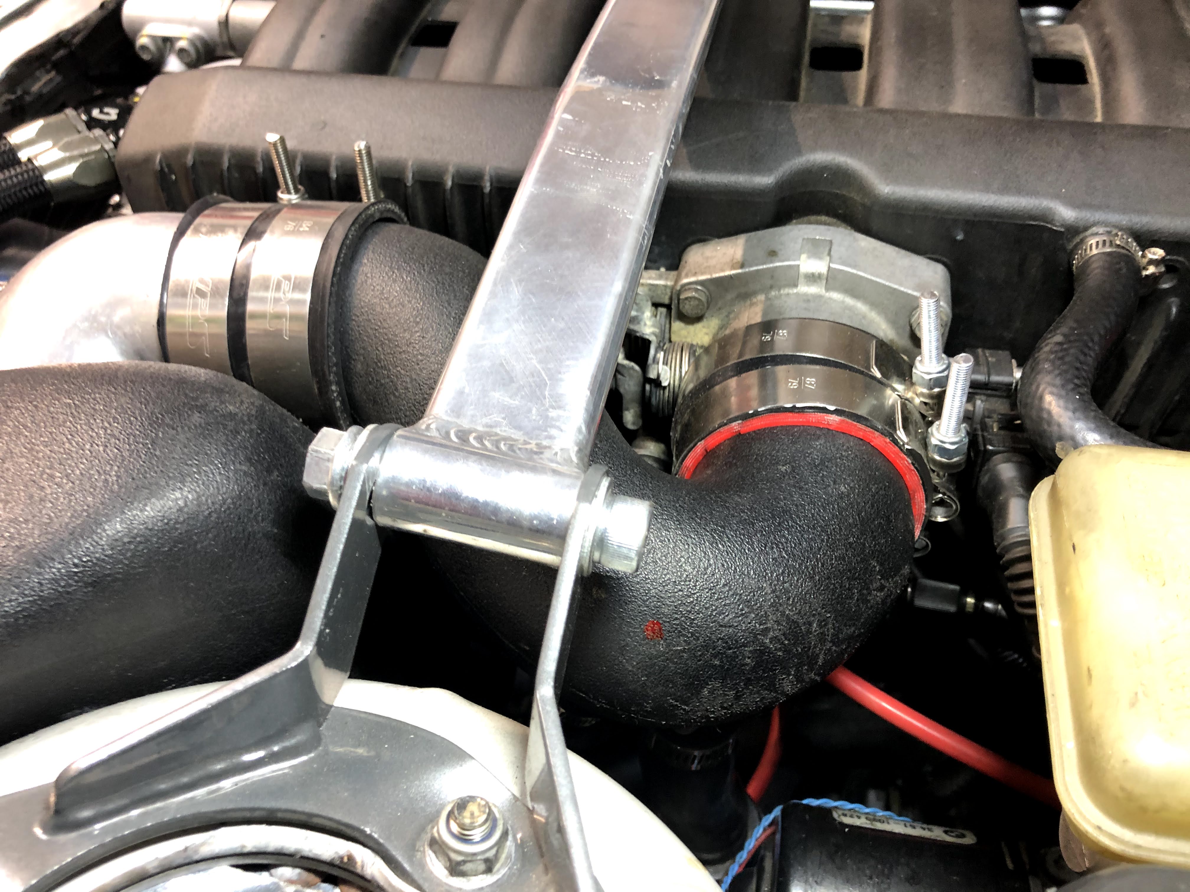
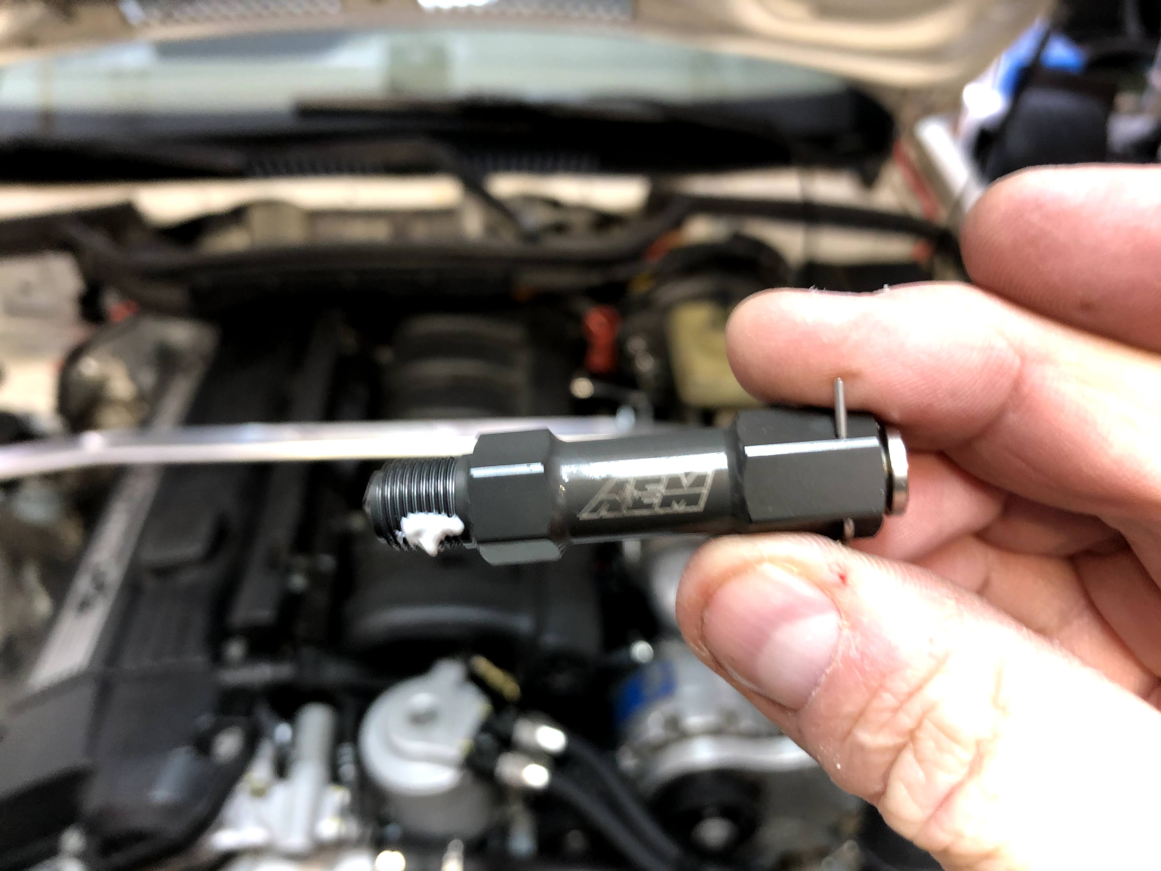
The injection nozzle needs to be mounted after the supercharger but prior to the throttle body. AEM advises that it should be placed 6″ – 8″ before the throttle body plate. The thick plastic charge pipe that I have coming from the Vortech supercharger is where the nozzle will be installed. After some measuring, and looking at possible locations, I decided to mount the nozzle where the red paint dot is in the photo above. This location is about 7.5″ from the throttle body plate and isn’t spraying directly into the opposite wall (unlike most locations in the charge pipe).
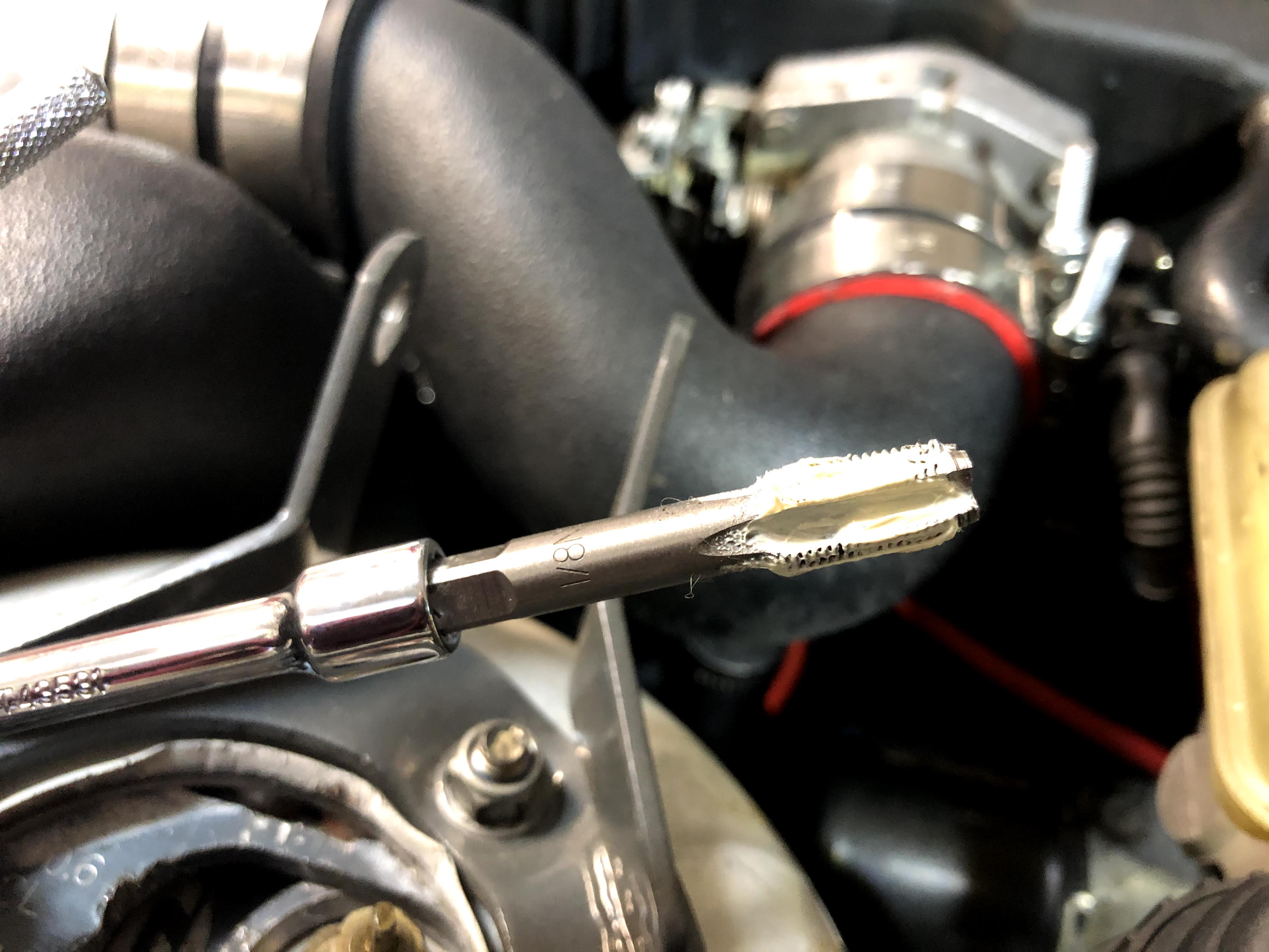
I drilled a hole in the plastic pipe and then used a 1/8 NPT tap, coated in white grease, to tap the hole. The grease attracts/traps all the plastic particles so that none make it into the charge pipe. Alternatively, I could’ve just completely removed the charge pipe and tapped it while sitting on a bench, but that’s a hassle and it’s tough sometimes making sure all the screw clamps are positioned correctly and tightened perfectly on the silicone couplers.
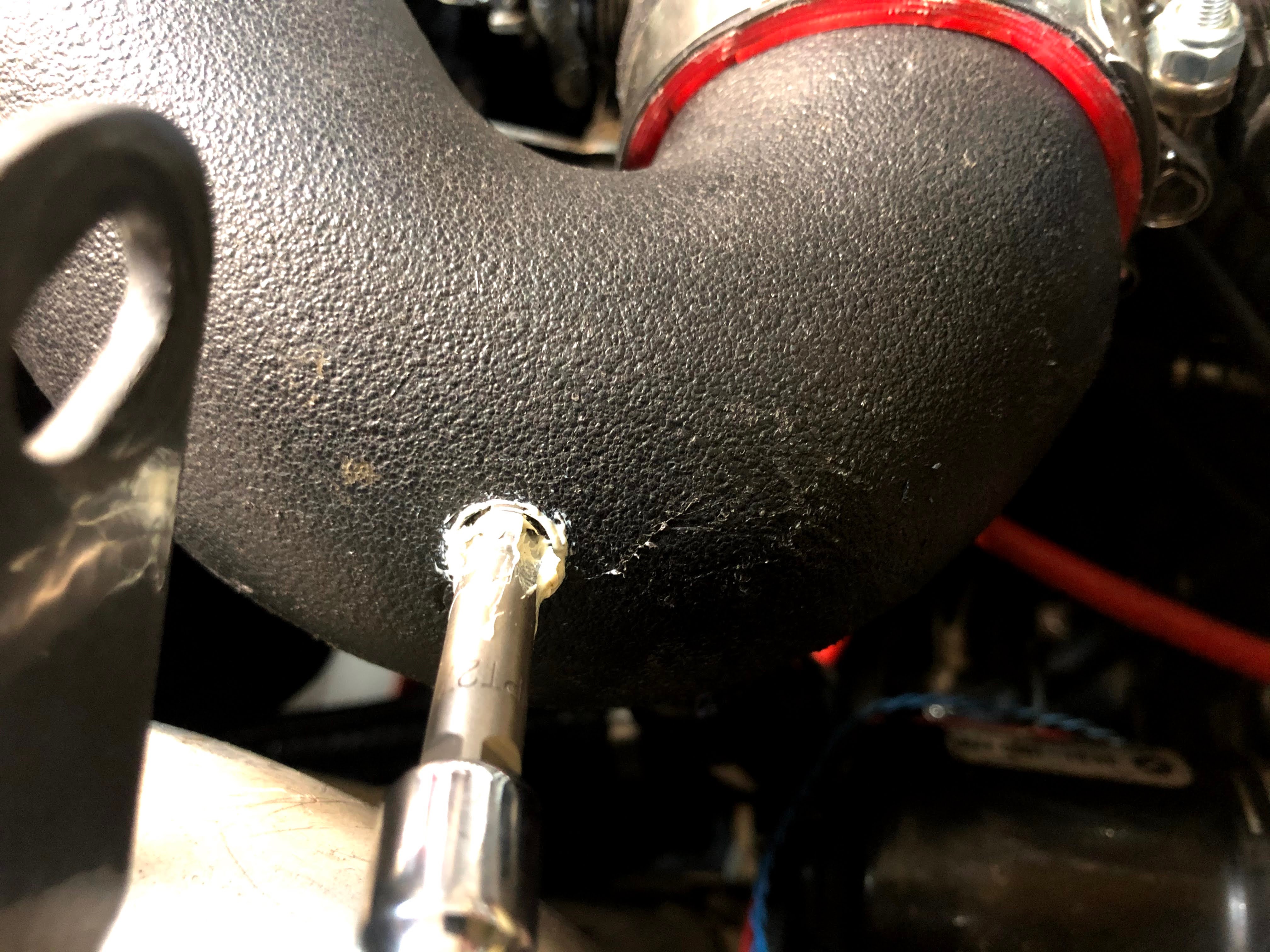
Just tapping away! Slow and steady…
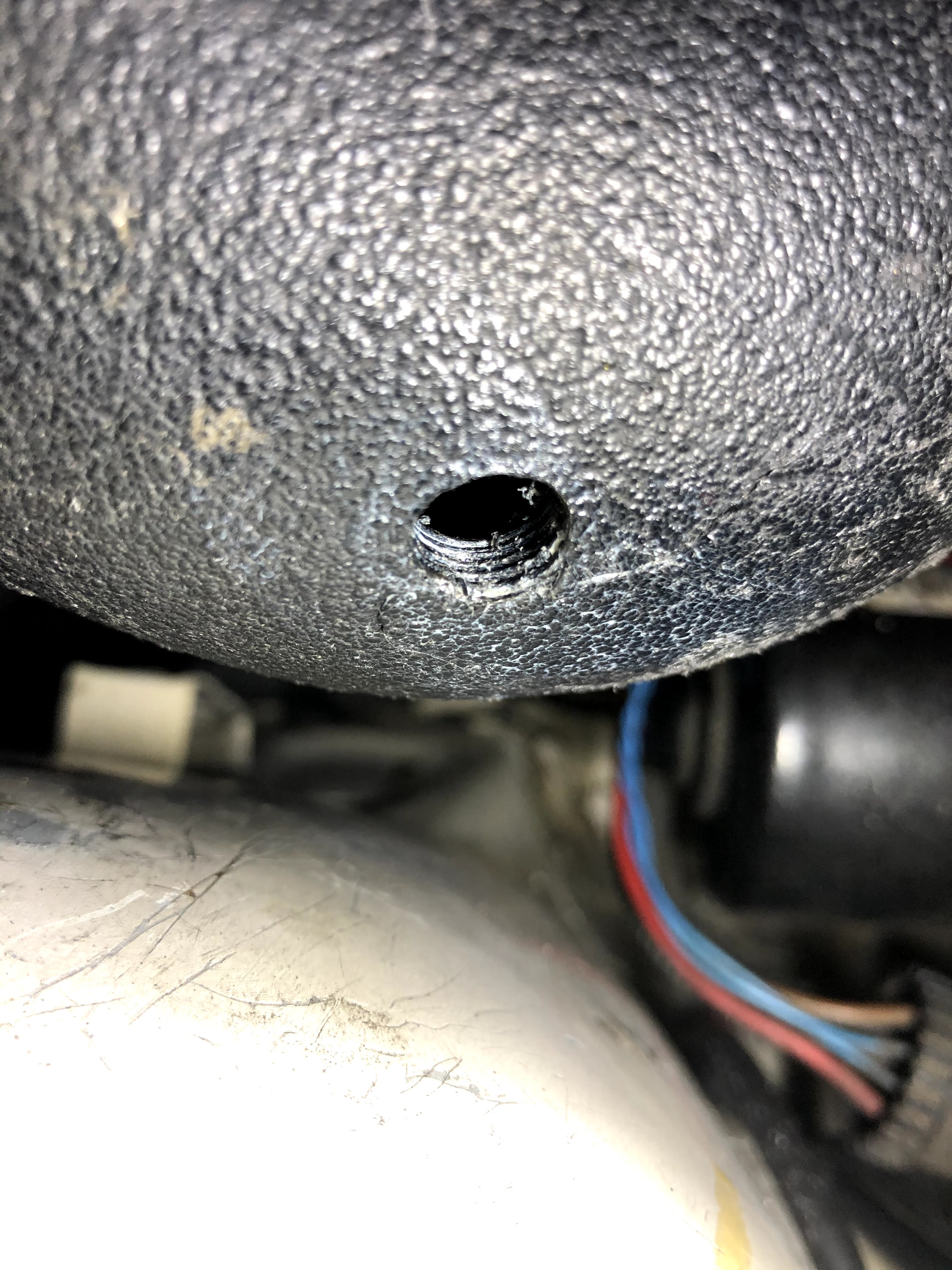
In the picture above you can see the final threaded hole in the plastic boost pipe. Notice how there are actually around 4 full threads which should be plenty to securely mount the nozzle.
I installed a little high temperature thread sealant on the injection nozzle to make sure it won’t come loose and no pressurized air makes it out of the tapped hole.
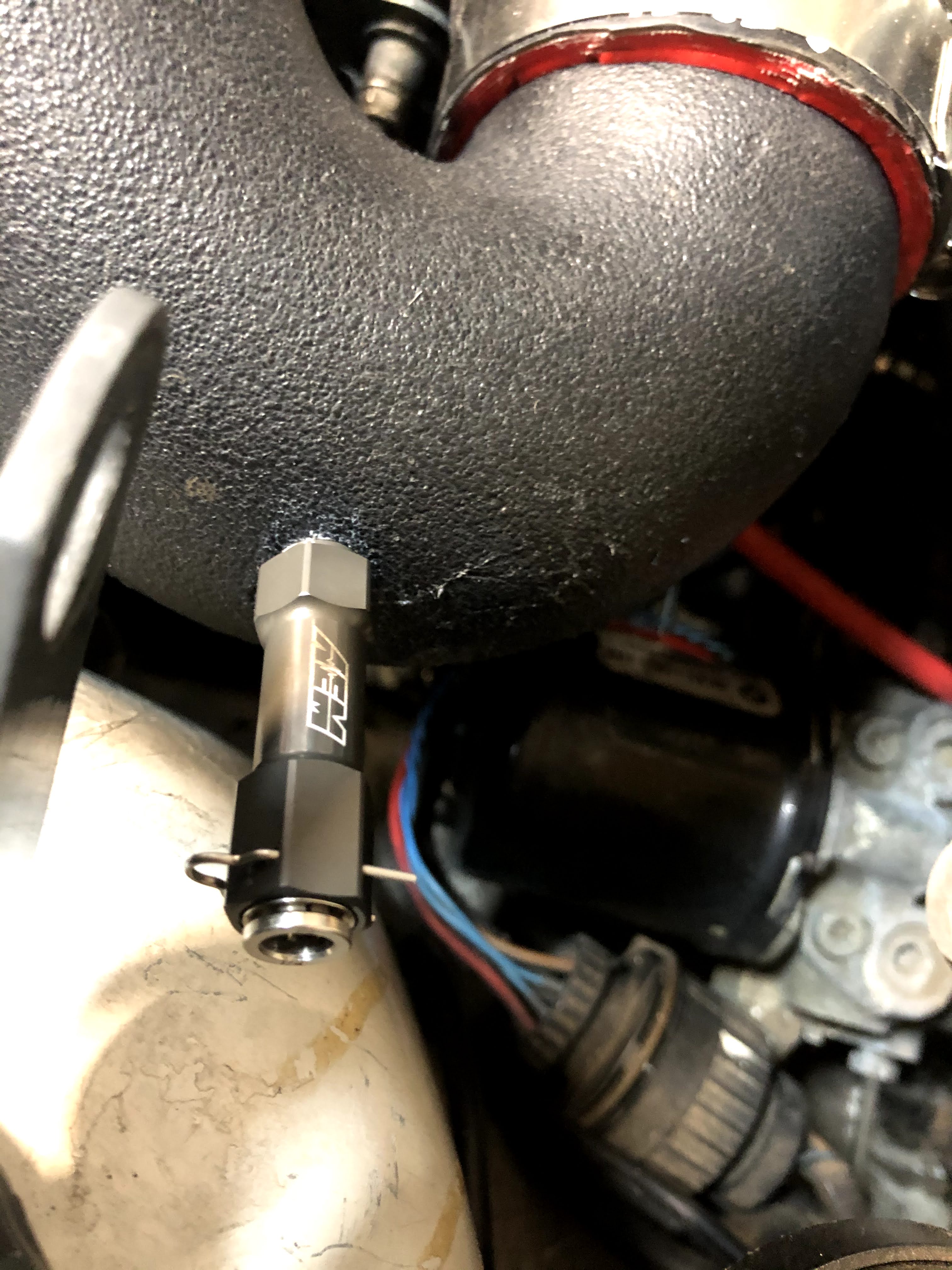
The nozzle is fully installed in the picture above. Don’t overtighten!
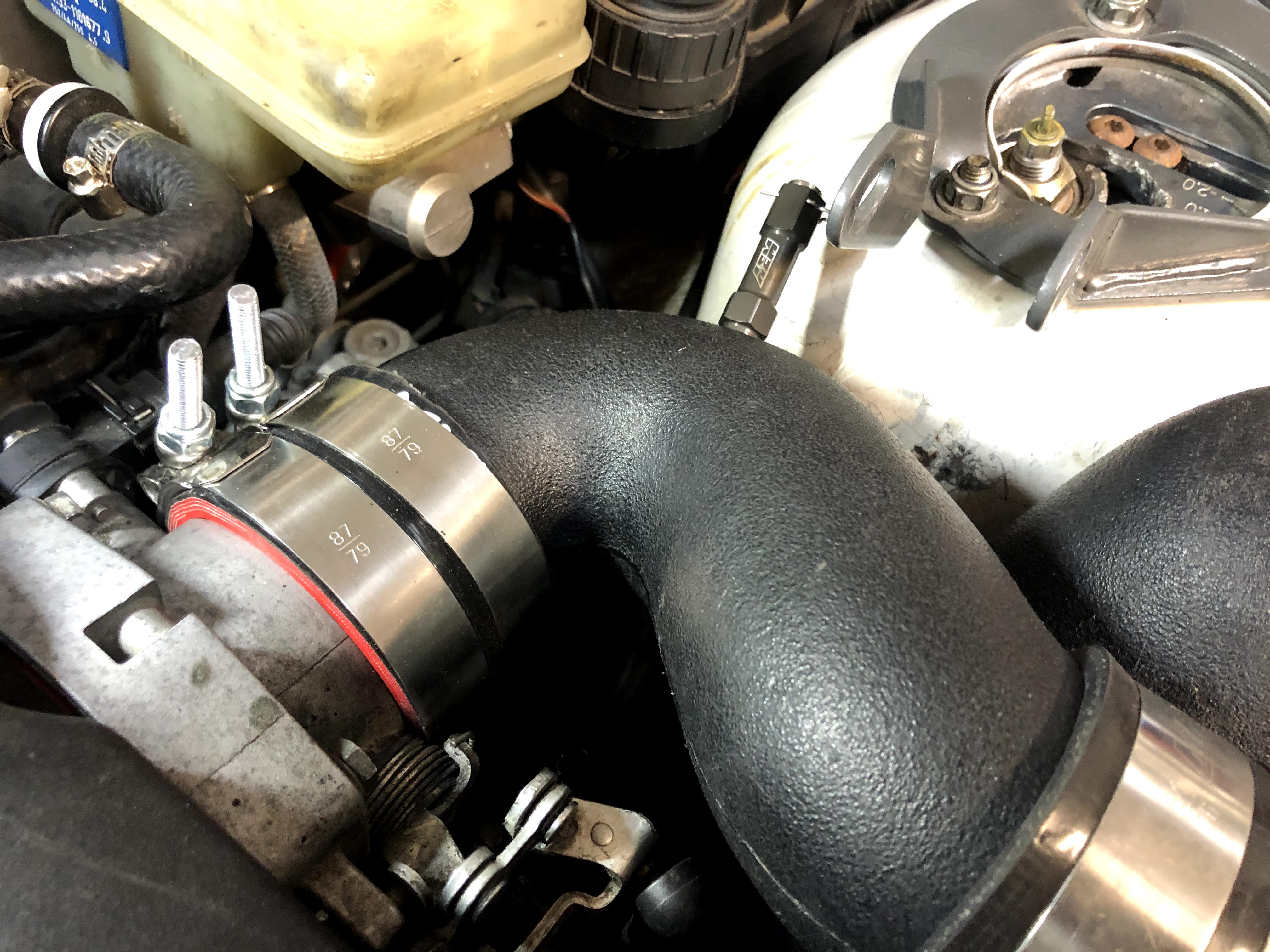
An alternate view of the nozzle location.
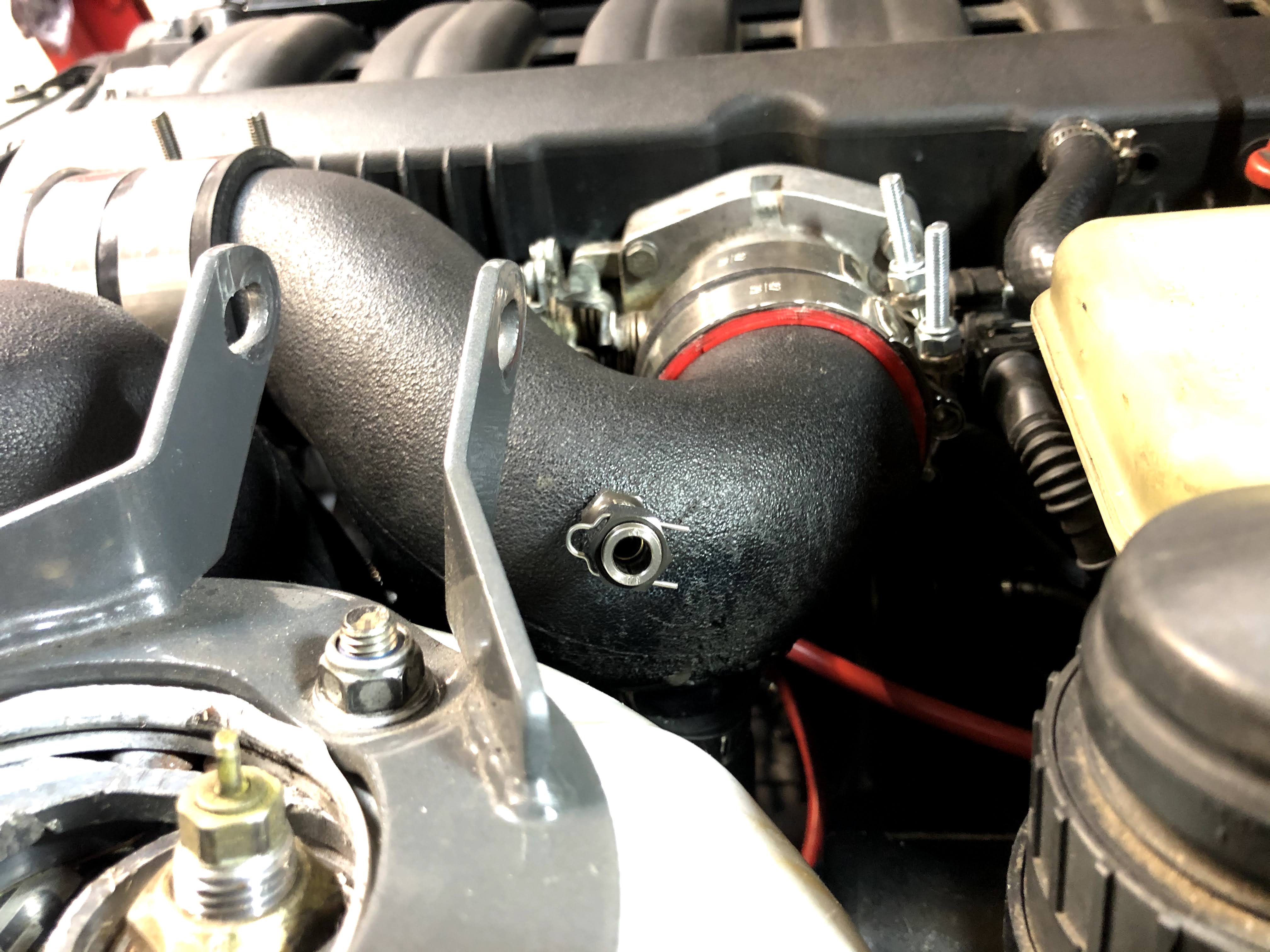
And one final view of the nozzle location.
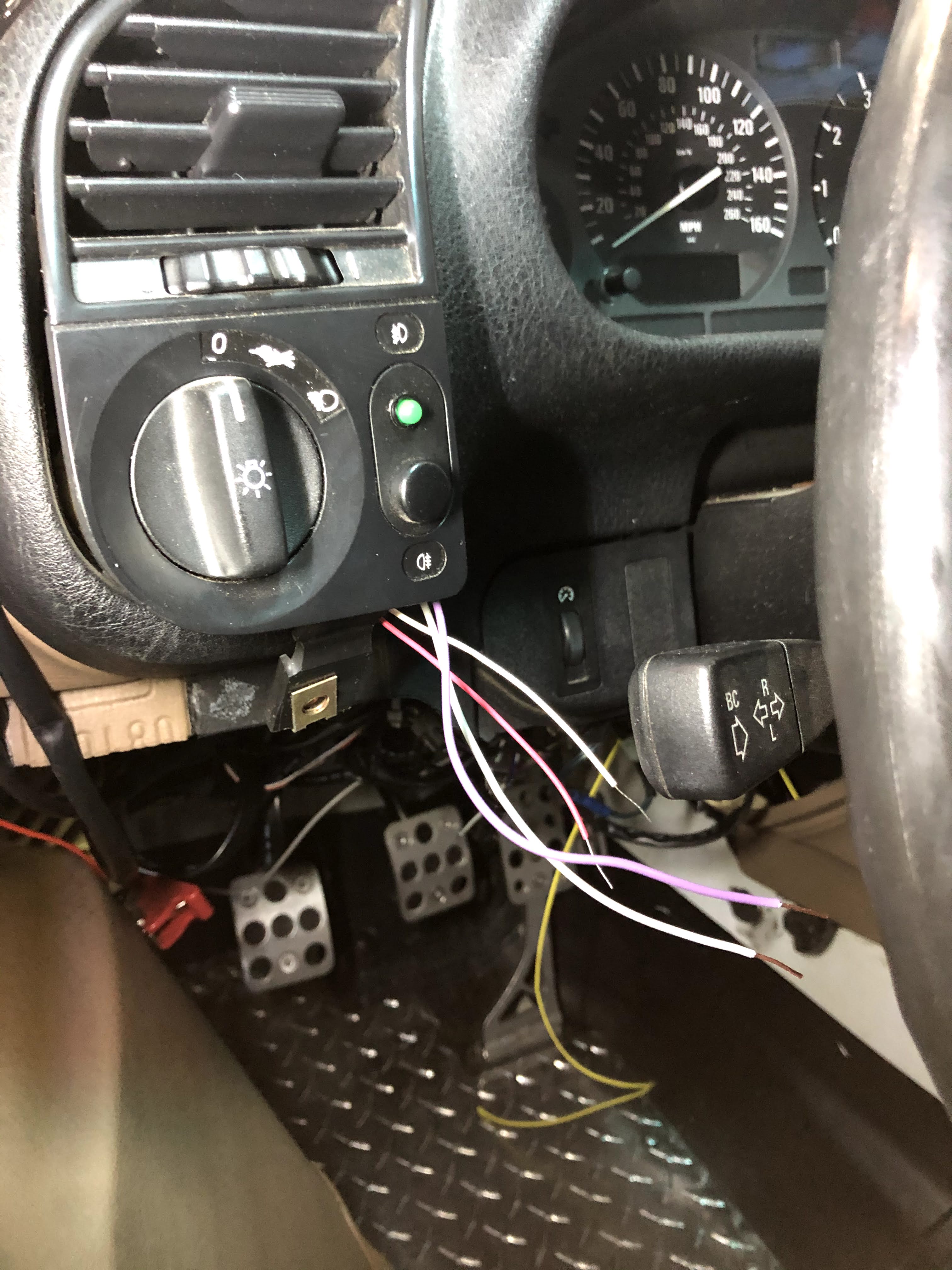
I then mounted the AEM system status green LED in the switch for the fog lights. It’s such a small LED and the fog light button was a very convenient location.
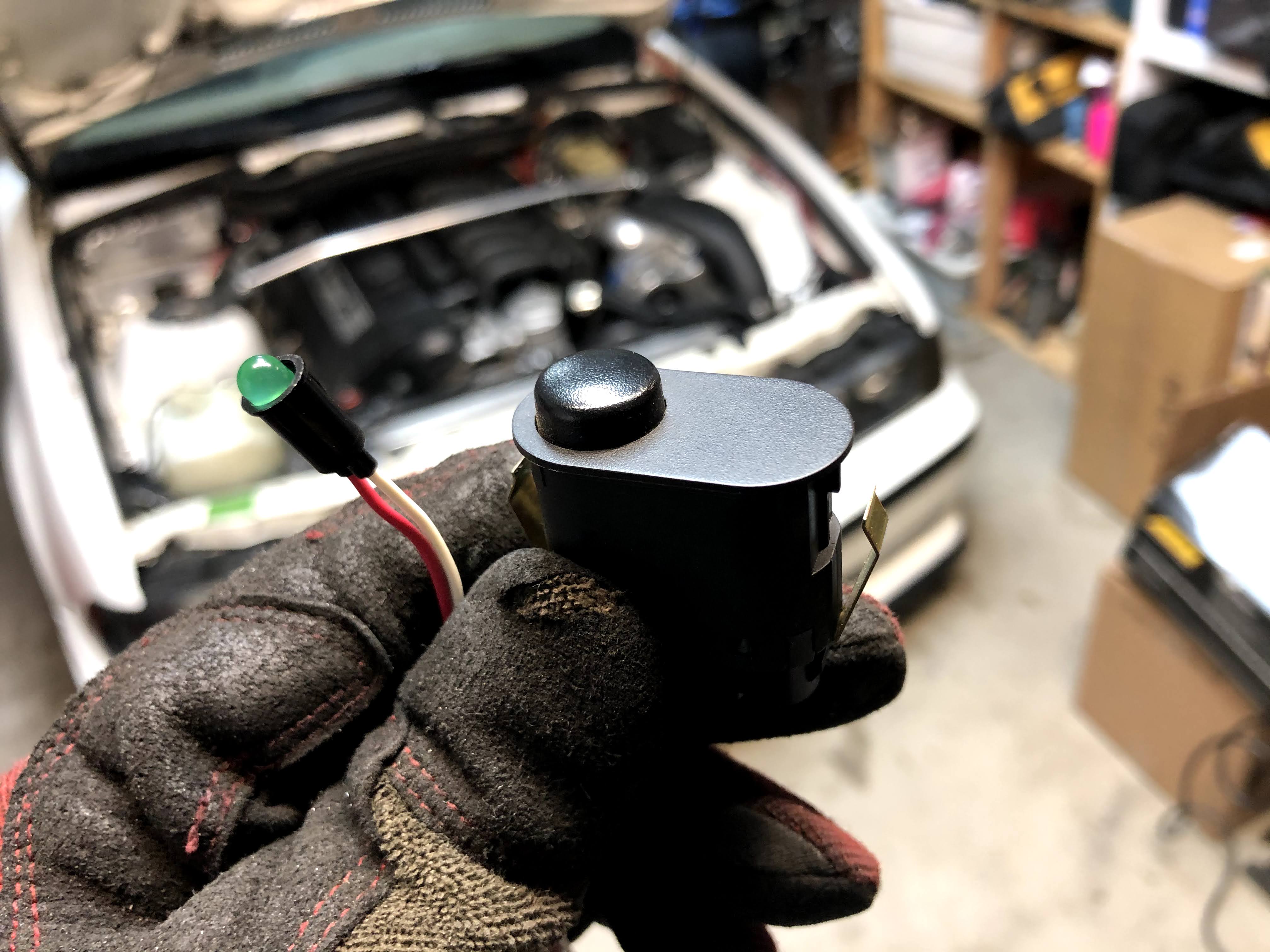
I’m not using my foglights, but even if you are, I believe that there should be a blank spot right below the button like in the picture above.
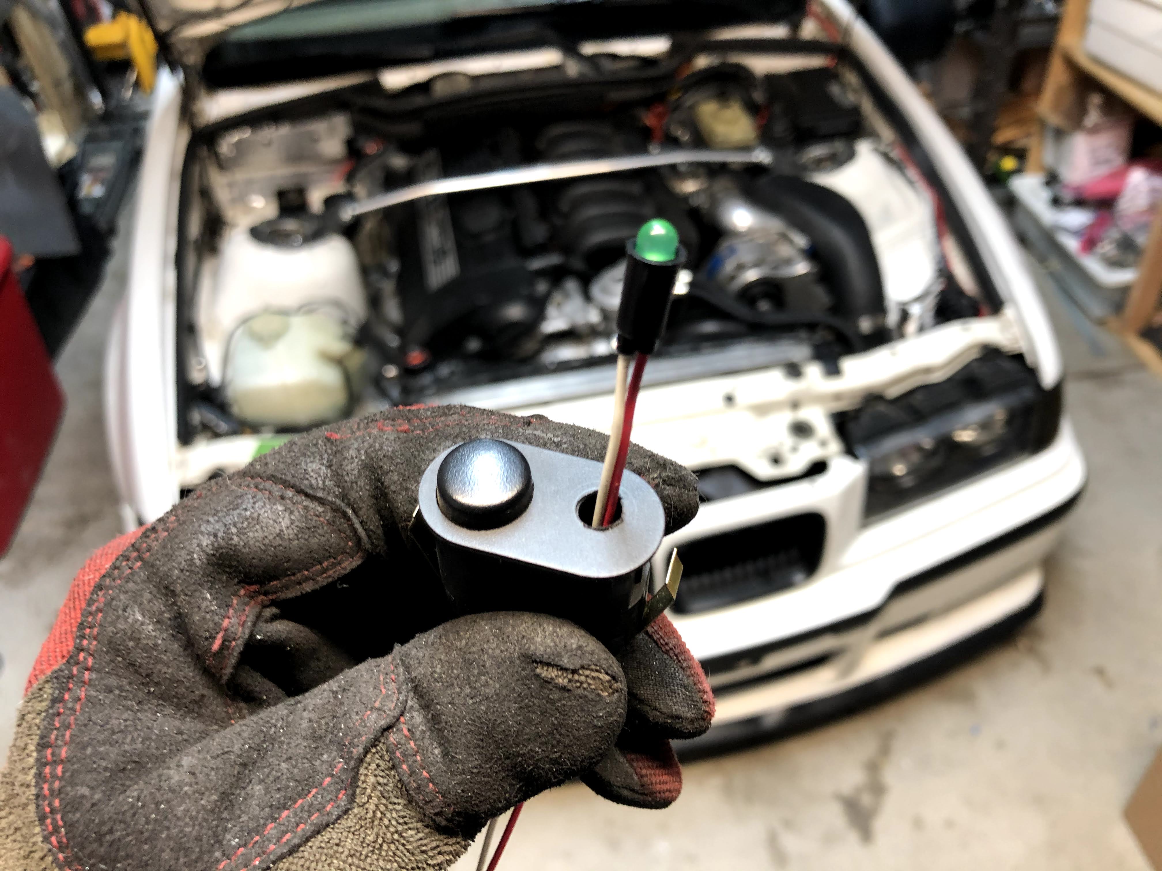
I just drilled a hole straight through with a bit slightly smaller than the LED housing.
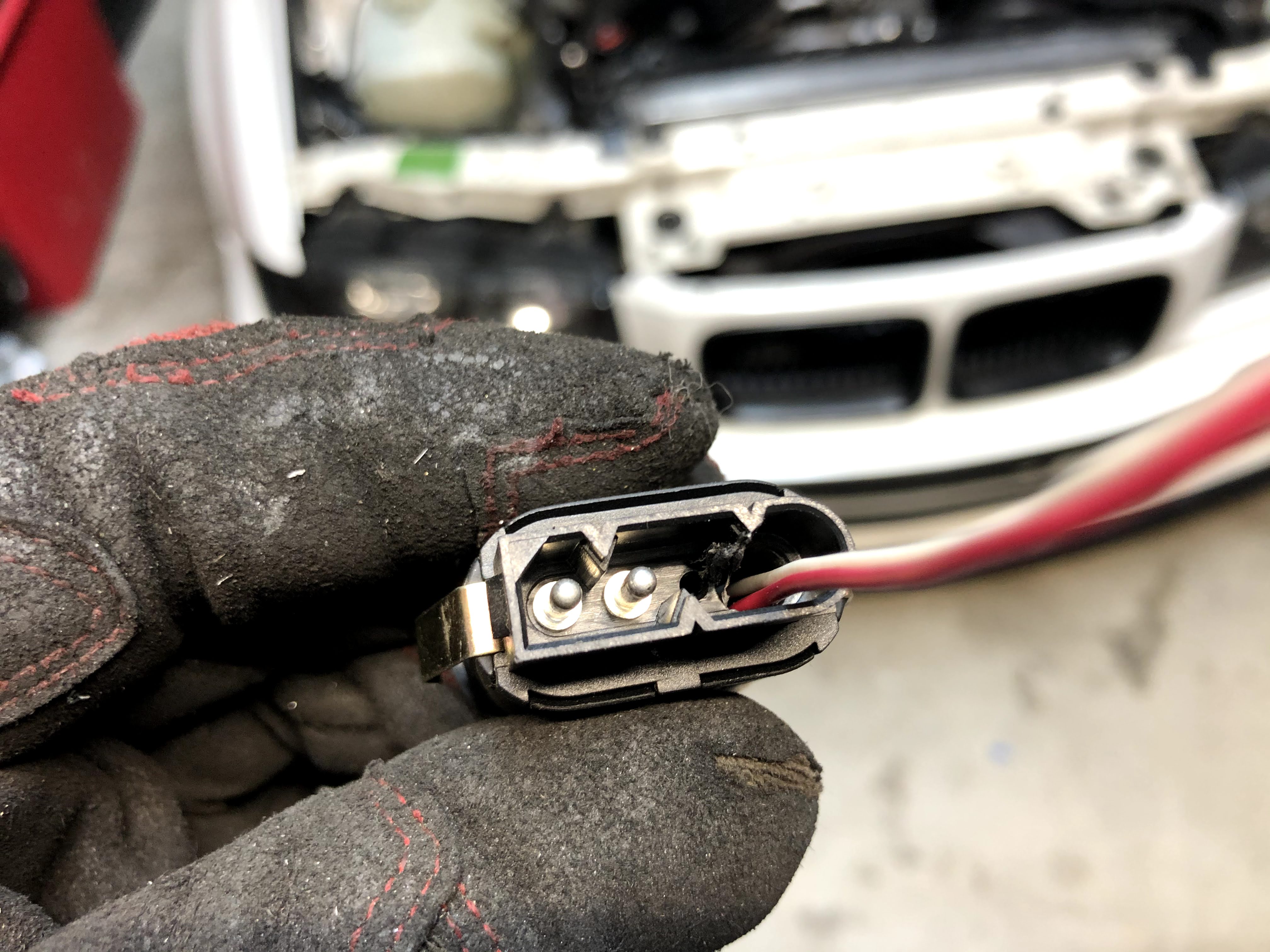
Here’s a rear view of the connector. Notice how I didn’t even get into the fog light pins.
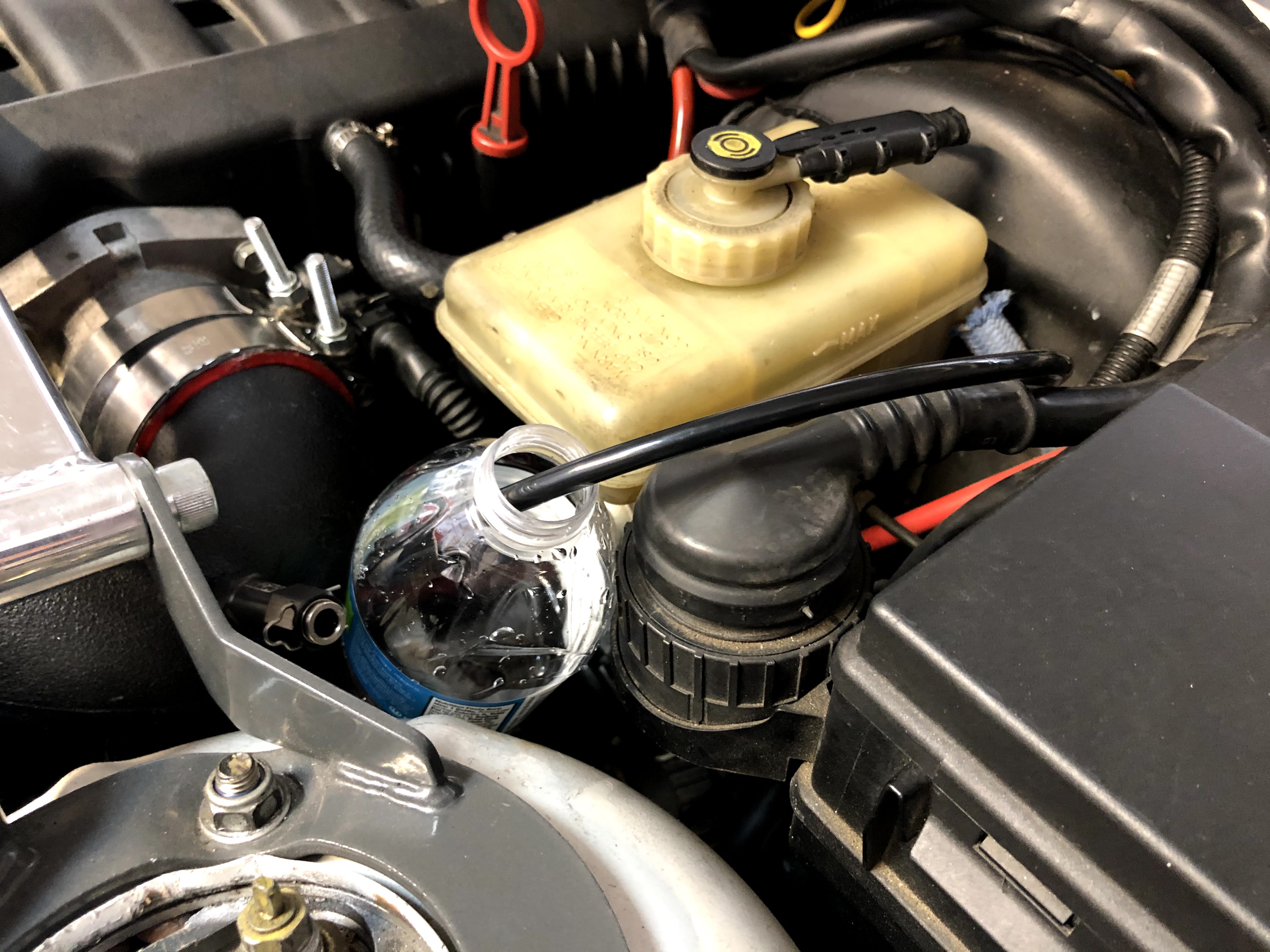
I then turned the ignition on (to provide power to the AEM system) and flushed it with water using the “TEST” button on the controller.
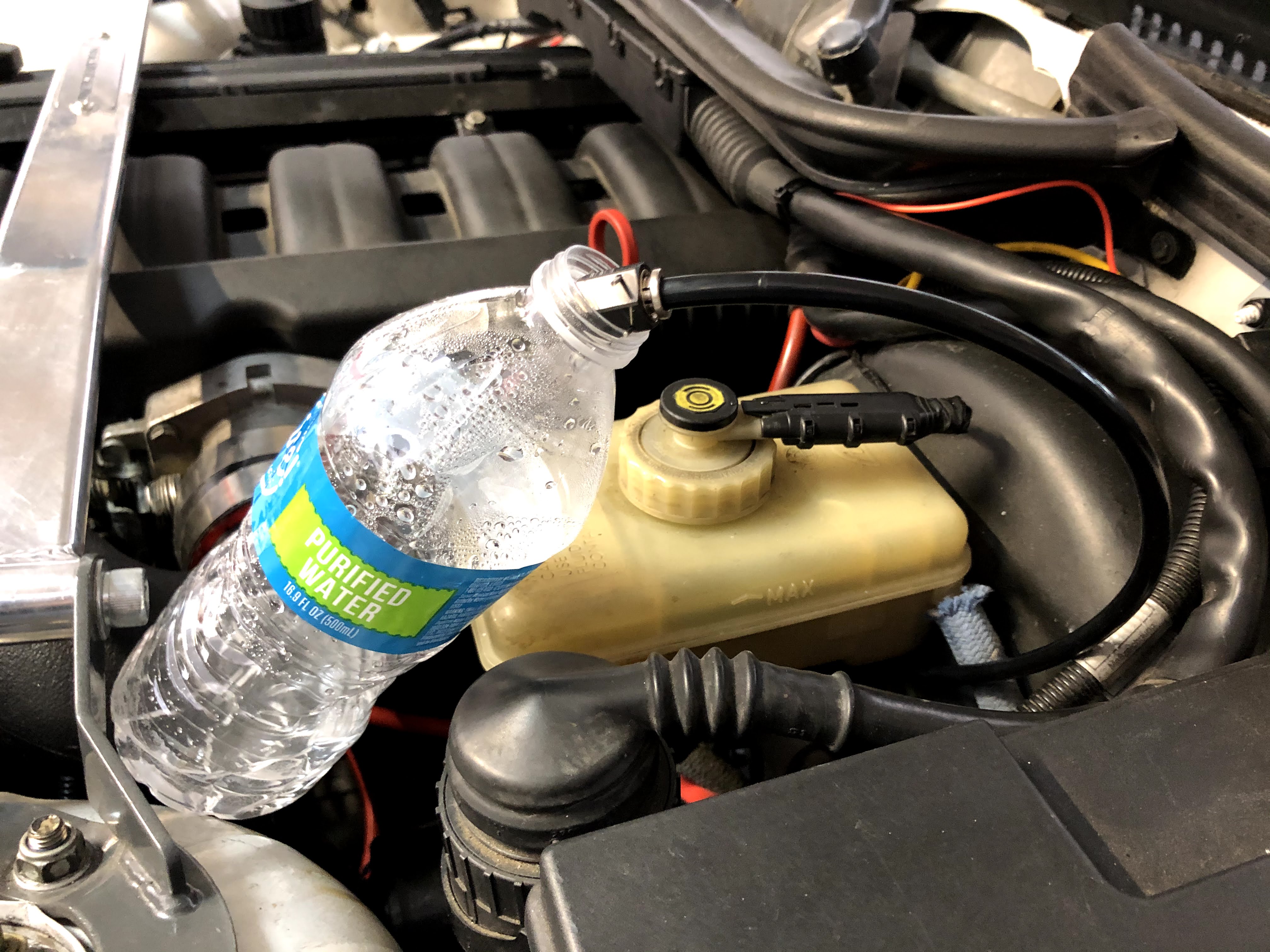
I then flushed with water and the injection nozzle attached…
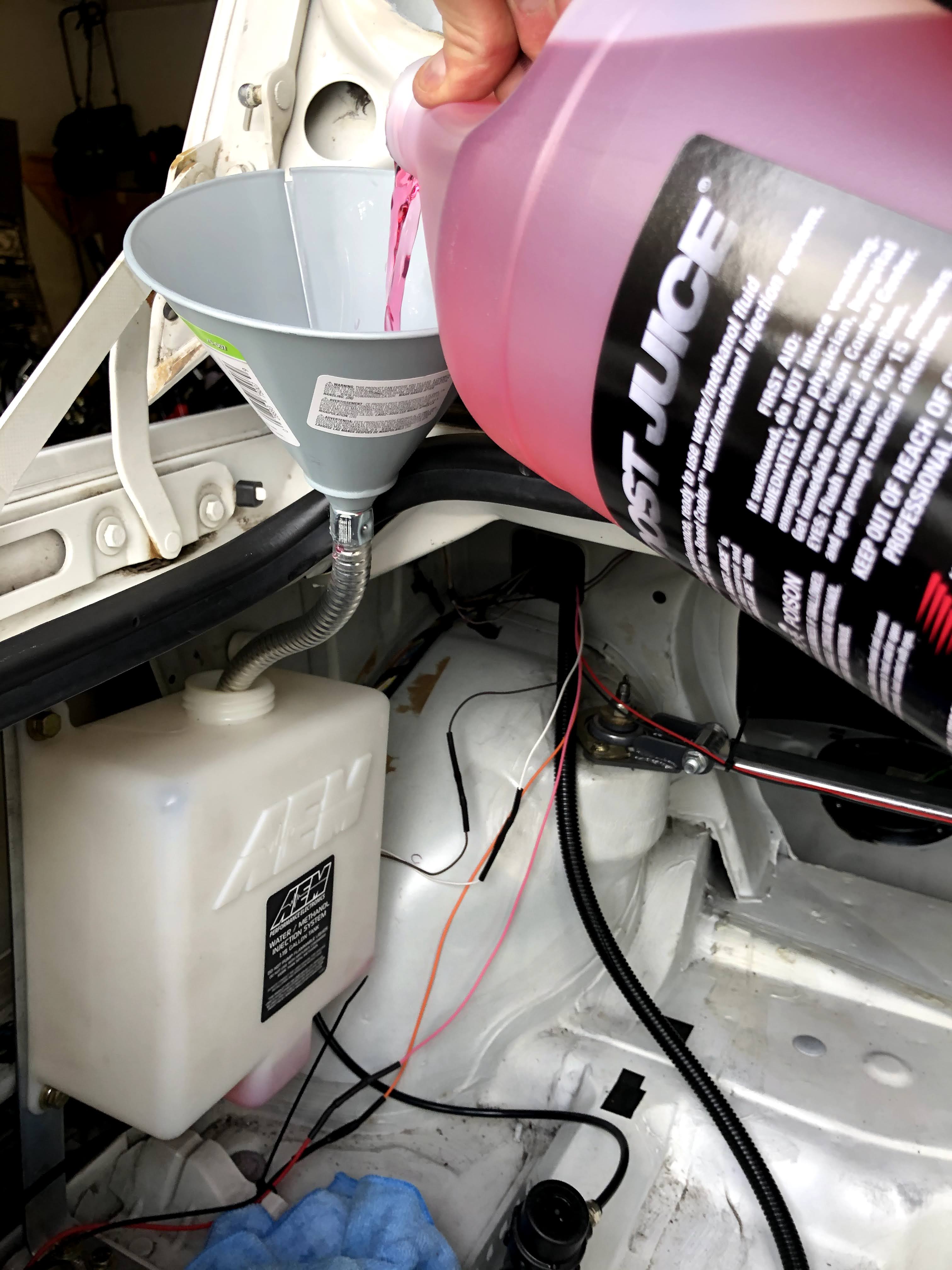
And finally, I filled it up the tank with Boost Juice.
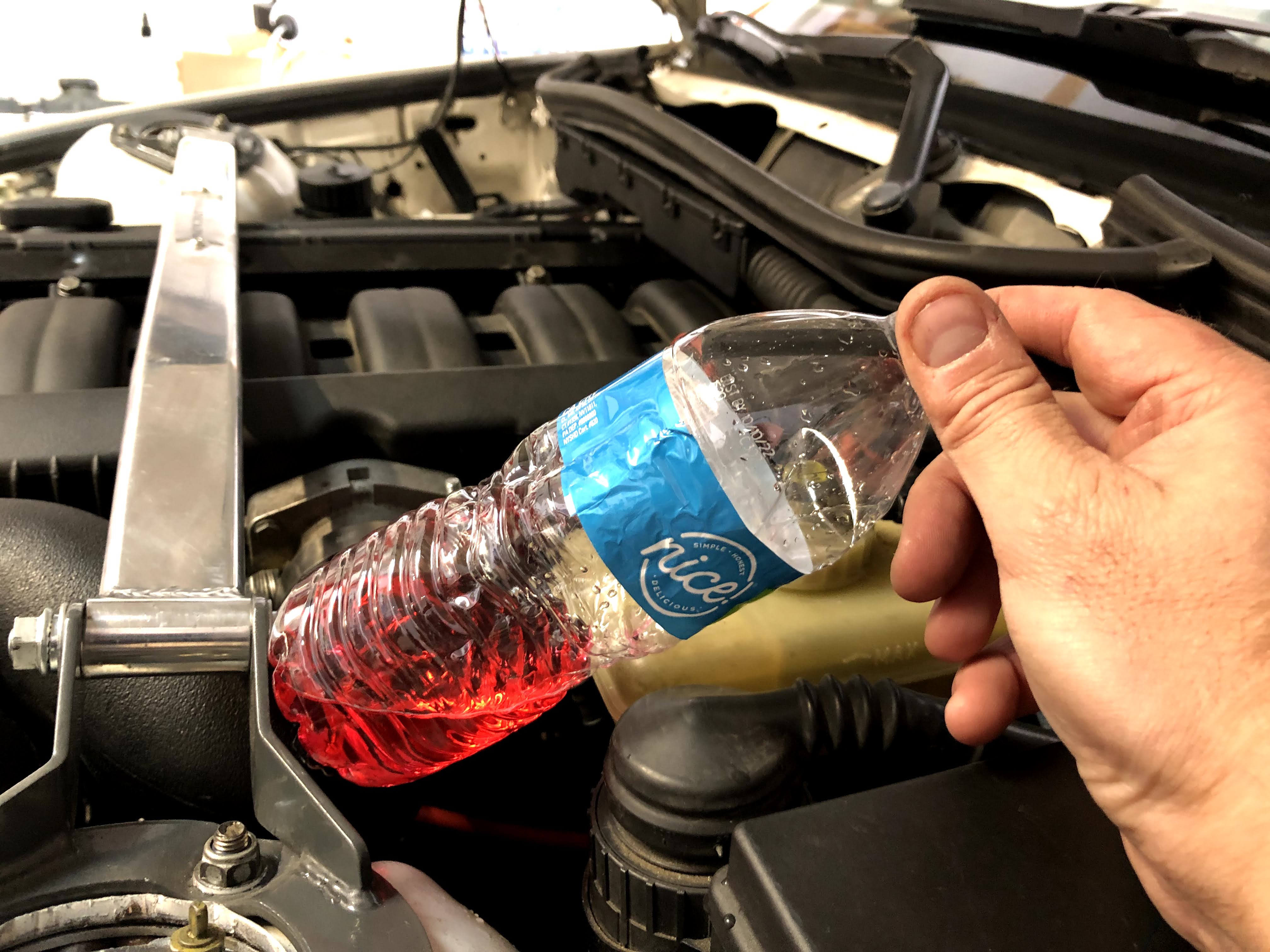
And sprayed until the Boost Juice made it through the whole system. The system was now fully primed and ready to rock!
I’m viewing this system not as a performance improvement, but instead as a way to extend the amount of time (hopefully indefinitely) that I’ll be able to maintain full supercharger performance on the track. I’ll most likely need to try different settings on the AEM controller for when I want the WMI to start and when I want it at full flow. I might also need to change the nozzle flow rate size. These are variables that I’ll only be able to nail down through trial and error when in full track conditions.
Overall, I’m very impressed with the completeness of the AEM kit, ease of setup and use, and value for the money. Highly recommended based on my initial impressions! There’s always another project so be on the lookout for what’s next…
If you liked the information in this page, be sure to check out my Developments page for my most recent posts! Every single post is listed with a link on the Headquarters page.
Links:

I’m working on something simmilar, what was the level of boost. That you had the pump set to run at?
LikeLike
John, I’ve experimented with different setting but the current setting is that the WMI starts at 3psi and is full force at 10psi. It seems to be working well so far.
LikeLike
Thanks for the reply! I talked to a friend of mine and he mentioned his setup was set up in the same way but different injection settings. He experienced high temps on cylinder 1 and 6 and detonation on 6z It ended up with a head gasket failure between the two. He ended up building his own water to air intercooler. Im trying to figure out what I should do for a daily for moderate to spirited driving here in Florida.
Btw thank you for your posts, I had recently bought a used dinan sc kit to install on my car, and without your article on the install I would have skipped a few steps.
I appreciate you!
LikeLike
John, I’m glad you’re finding the posts helpful!
Tough break for your friend but I’m not suprised that he saw issues with cylinders 1 and 6. The intake manifold on the M50/M52/S52 engine family has the throttle body right in the middle so the cylinders at the extremes (1 and 6) would see the least amount of Water Methanol. Even though the WMI nozzle is trying to atomize the mixture as much as possible, it’s not fully a homogenous mixture and the intake manifold on these engines isn’t made for a “wet flow”. The newest AEM nozzle does a better job than ever but it’s still not perfect.
Adding a water-to-air intercooler or air-to-air intercooler would definitely be the way to go to completely eliminate issues with charge air cooling. As you see though, space is very tight in the E36 engine bay to plumb a setup like this. There have been some kits developed in the past and others have tried to make their own as well. For a car that sees extensive track work with extended sessions, true intercoolers are the way to go.
However, for what you described as moderate to spirited daily driving in Florida (hot!), I think WMI would be added insurance and not even a necessary requirement. Good luck!
LikeLike
Hi again Brent, the kit finally came in and I wired everything up and plumbed it all together for a test. It all worked flawlessly! Now my biggest problem is just fabricating a mount for the tank in the back. Im probably going to make a flat panel to mount the tank and pump to and then secure that to the back of my seats or in a similar position to your setup. But it would be on a quick release or a peg system so I can remove it if I ever need more space for whatever reason.
By the way I’ve been meaning to ask you. What pulleys are you running and what boost are they producing on your setup? I believe mine are the standard pulleys because I am seeing 5.5/6 psi
But it spools incredibly quickly .
If you run a smaller pulley which one is it and what belt are you using for it?
Thanks again!
LikeLike
John, great to hear that you had success with the first start-up! The methanol tank is definitely a bit tricky to mount, making it a quick release is even trickier. Good luck with that.
I’m running a smaller pulley (2.87″) only because I live at 6000’+ elevation and the air is so much less dense. Thus, the supercharger needs to spin faster just to create the same amount of boost. I get around 9 psi at 7200 rpm with that pulley. At sea level, that pulley would probably make 12+ psi.
I’m using a Gates K060785 belt that’s 2007mm (79.034″) in outer circumference. Remember that I don’t have a power steering pump though. If you’re still using your power steering pump then you’re going to need a longer belt.
Feel free to ask any further questions as I’m sure others are wondering the same things that you are. Thanks.
LikeLike
Hey Brent, I have had this same setup installed on my S52 for nearly 2 years and I had a few questions for you. What size nozzle did you ultimately go with? I have played with the 250cc and 500cc and both are somewhat difficult to know if it makes a difference. I’m running just over 6psi at redline, and I mix roughly 20/80 (meth/water). I’m starting to wonder if the 500cc is a little too much and possibly quenching the spark as I will sometimes get misfires near redline. I start to spray at 3psi and have played with “full” all the way between 6psi and like 15 (to try and diagnose a possible quench). Have you ever experienced this issue? I’m running regular copper plugs and wondering if I should change those to something else.
LikeLike
I’m currently running the 500cc nozzle (the medium one). I’m only using WMI in order to prevent detonation, not for added power. So, you really wouldn’t notice much if it’s doing it’s job correctly. I think of it as an enabler of increasing boost, especially without an intercooler. I’m currently still running it from 3psi roll-in and then full spray at 10psi. I’ve not seen any misfires yet when playing around with it. I’m still running the “Boost Juice” and it seems to be working well. I’m also still running the NGK 4776 BKR7E-E spark plugs and they haven’t given me any issues. Something to look at would be your AFR. Running too much WM will can increase the richness of your AFR by a good point or so from what I’ve seen in my own experiments. You could also play with your spark plug gap (decreasing it). Good luck!
LikeLike